When the brake switch branching wire harness
⑦
cannot be or is not used
09. Connect the + wire (red) of the USB power supply body
①
to the brake switch branching wire harness
⑦
.
If the + and – wires of the USB power supply body
①
are reversed, the reversed-connection prevention feature will cause
the fuse to blow. If the fuse blows, replace the fuse.
10. Connect the cable to the negative battery terminal. Use a tester to identify the location where the – battery cable (ground) is
connected to the vehicle with an M6 or smaller bolt. After identifying the ground, disconnect the cable from the negative battery
terminal.
※
The location of the – battery cable (ground) is where the resistance is nearly 0 Ω.
11. Fasten both the – wire (black) of the USB power supply body
①
and the – battery cable (ground) identified in step 10 with the bolt.
12. Use a cable tie
⑨
to secure the transformer
③
to the vehicle.
13. Connect the cable that was disconnected before performing the work to the negative battery terminal.
14. Install any vehicle parts that were removed before performing the work.
15. Turn the handlebar to the left and right to check that the fuse holder wires are not pulled and that no parts come into contact with
the product.
※
A pulled wire can lead to problems such as sudden operation failure.
16. Check that there are no abnormalities; if there are no problems, the work is completed.
17. Connect the cable to the negative battery terminal. Use a tester to identify the wire that carries 12 V when the ignition switch is
turned ON. After confirming, turn off the ignition switch and disconnect the cable from the negative battery terminal.
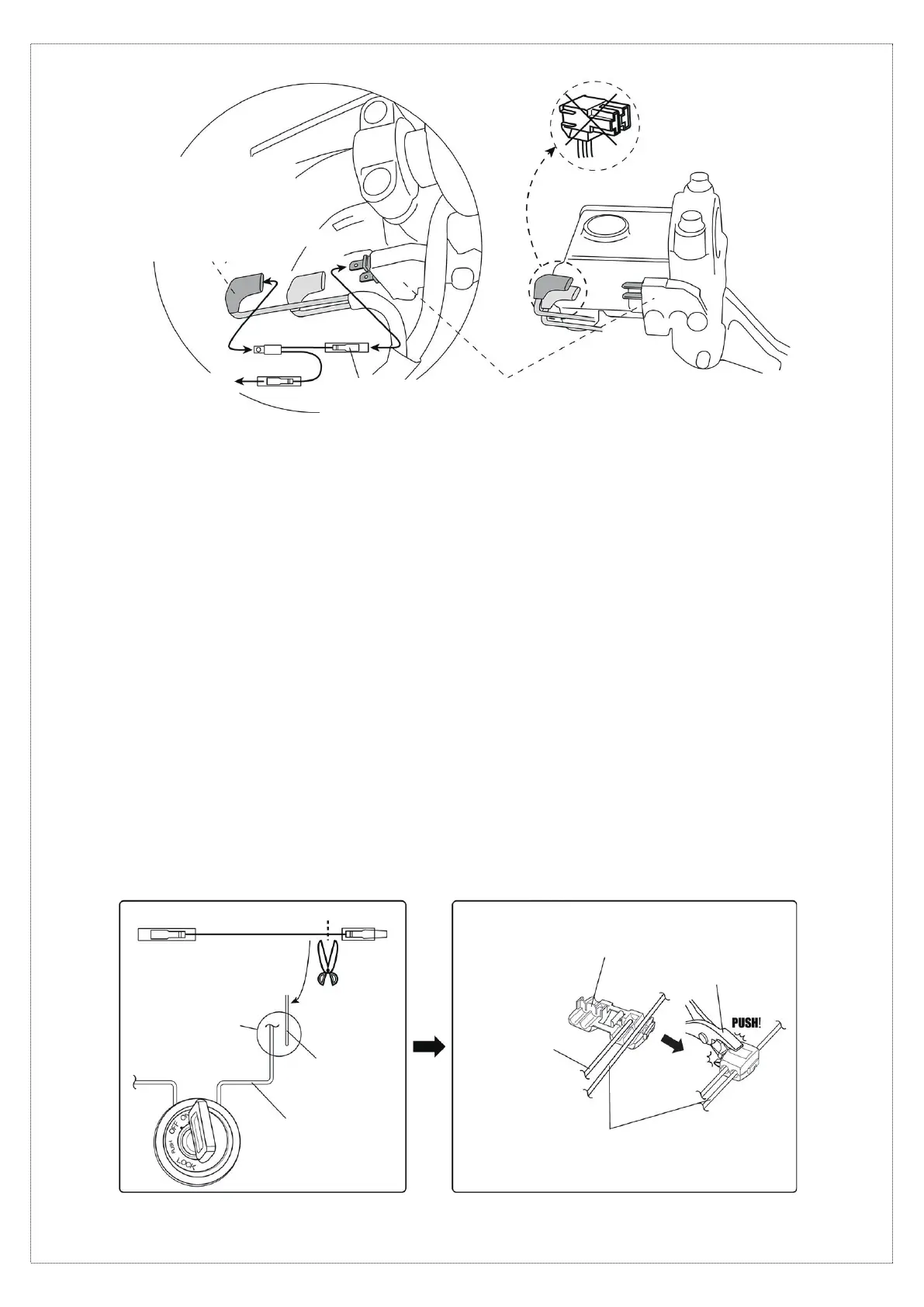
18. Cut the male connector end of the extension wire harness
⑥
to adjust its length.
19. Use the wire connector
⑧
to connect the extension wire harness
⑥
to the wire identified in step 17.
※
For details on using the wire connector
⑧
, refer to the diagram below.
3/4
[Branching the brake switch power supply]
[NG]
To the + wire (red) of
the USB power supply body
①
Wire that carries 12 V when the ignition switch
is turned ON.
※
Incorrect installation will cause
symptoms such as power being supplied only
when the lever is squeezed.
※
Cannot be used if the connection is
made with a coupler. Go to step 17
⑦
Brake switch
branching wire harness
Brake switch
[Sample power supply wire connection]
[Using the wire connector
⑧
]
⑥
Extension wire
harness
Cut
Connect with wire
connector
⑧
, etc.
Wire that carries 12 V
when the ignition switch
is turned ON
⑥
Extension wire harness
Pliers
⑧
Wire connector
⑥
Extension wire
harness
Wire that carries 12 V when
the ignition switch is turned ON
20. Connect the + wire of the USB power supply body
①
to the extension wire harness
⑥
.
If the + and – wires of the USB power supply body
①
are reversed, the reversed-connection prevention feature will cause
the fuse to blow. If the fuse blows, replace the fuse.
 Loading...