Do you have a question about the DayTronic 5M78 and is the answer not in the manual?
The Daytronic Model 5M78 is a single-channel AC Strain Gage Conditioner Module designed for precise measurement in demanding environments. Its core function is to condition signals from phase-sensitive carrier-amplifier designs, making it particularly suitable for applications involving transformer-coupling to transducer bridges, such as rotary-transformer torque sensors. Beyond these specialized uses, it excels in conventional installations where high sensitivity is paramount or where the electrical environment is prone to noise.
The 5M78 operates by responding exclusively to the modulated carrier frequency, effectively rejecting extraneous voltages that can introduce errors in DC systems. This capability is crucial when there's a need to "blow up" a specific portion of the transducer's range, allowing for enhanced resolution and accuracy. The module features user-adjustable phase and symmetry controls, enabling fine-tuning for optimal performance with various transducers and setups. Calibration of the 5M78 can be performed using either a "two-point (dead-weight)" method or a shunt-calibration technique. An internal 59 kilohm, 1% shunt calibration resistor is provided for convenience.
| Brand | DayTronic |
|---|---|
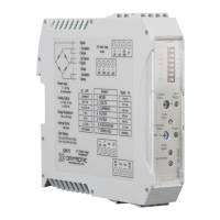
| Model | 5M78 |
| Category | Control Unit |
| Language | English |