DriveRack
®
/ZonePRO
™
User Manual
4
ZC-Remote Control Wall Controllers
USER GUIDE
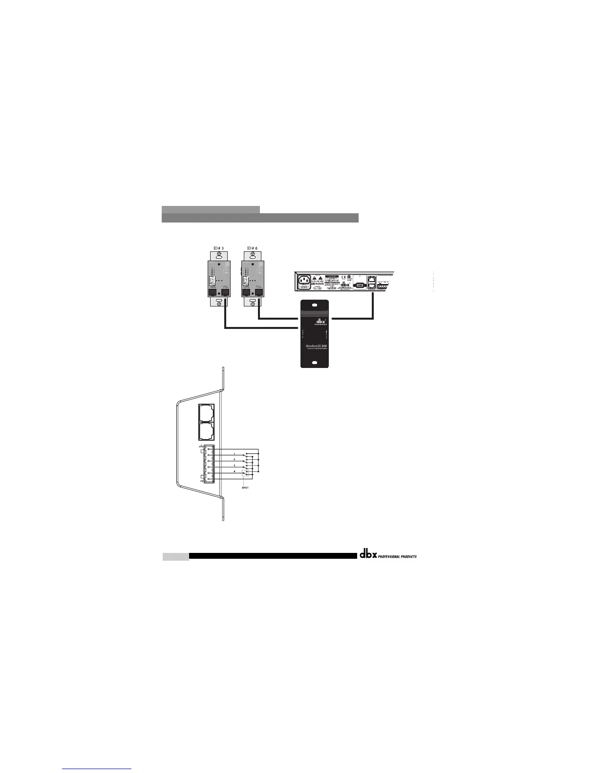
Diagram C
Diagram D
ZC-4
ZC-4 Binary App notes
SW4 SW3 SW2 SW1 Hex Setting
00 0 0 0 0
00 0 1 1 1
00 1 0 2 2
00 1 1 3 3
01 0 0 4 4
01 0 1 5 5
01 1 0 6 6
01 1 1 7 7
10 0 0 8 8
10 0 1 9 9
10 1 0 A 10
10 1 1 B 11
11 0 0 C 12
11 0 1 D 13
11 1 0 E 14
11 1 1 F 15
Switches SW1-SW4 correspond to switch inputs 1-4 on the ZC4's
EuroBlock connector.Each switch connected to the ZC4 must be a
Dual Pole Single Throw (DPST). One pole of each switch should
be connected to the ground reference on the ZC4's EuroBlock con-
nector while the other pole should be connected to the +V refer-
ence. Because there are four switch inputs, there are 16 possible
switch combinations. In the chart above, a "0" cooresponds to a
switch connected to +V reference, while a "1" cooresponds to the
switch being connected to ground. None of the poles should be
left hanging but should either be connected to +V or ground.