8
OWNER’S MANUAL
AIR FLOW BALANCING
All DCA units are shipped from the factory with the
airflow set at the standard CFM for your particular model
and .5 WC external static pressure E.S.P. Refer to DCA
specification sheet for more information.
To verify unit will deliver required CFM and adequate
E.S.P. when installed in your application, a simple check
must be performed.
An incline monometer, digital
monometer or pressure differential gauge must be used.
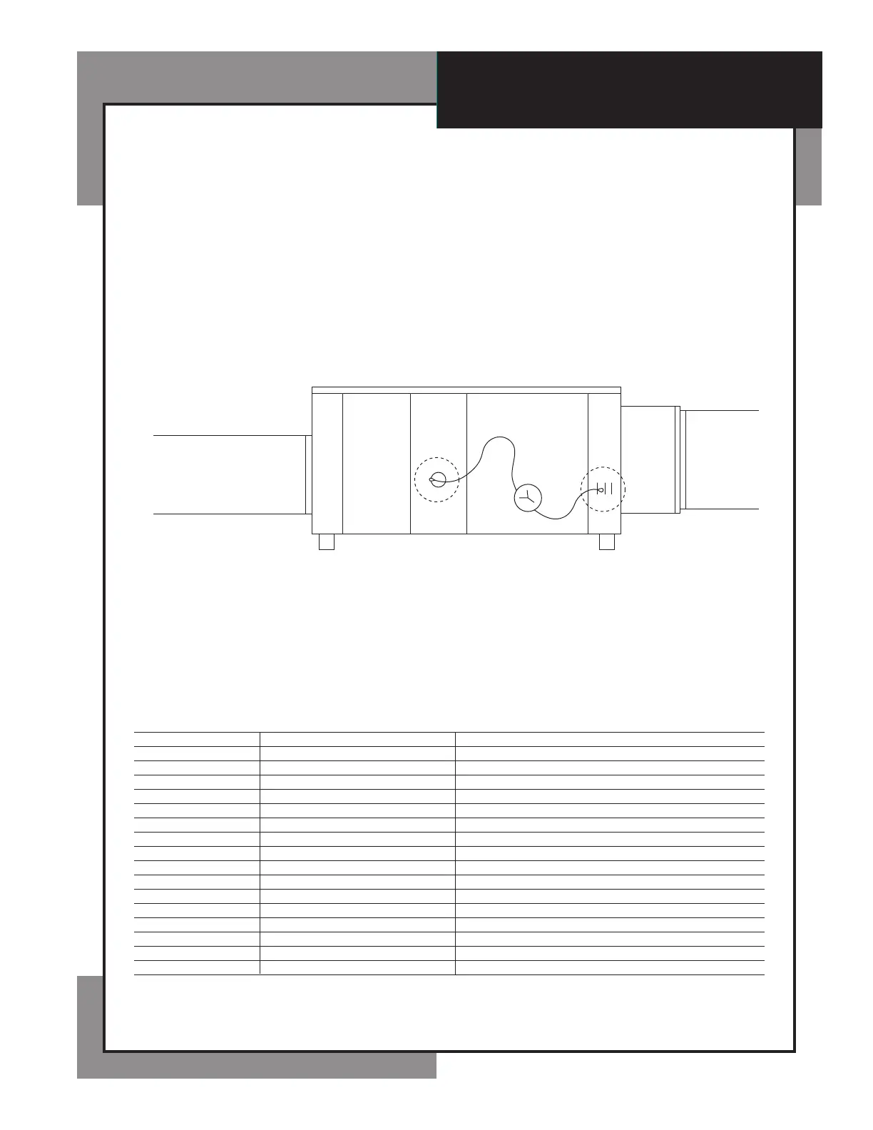
Chart A
Supply
Air Balancing Port Locations
Return
A
L
LO
B
HI
CHART A
Shows the location of the air balancing access ports and where to insert the HI and LO pressure tubes of the monometer or
gauge. Measure the pressure differential across the reheat condenser coil to verify air flow.
CHART B
Shows the static pressure drop across the reheat condenser coil at standard CFM for each DCA model at .5 E.S.P.
Chart B
STANDARD STATIC PRESSURE DROP (INCHES W.C.)
UNIT CFM AT .5 E.S.P.
DCA500 550
DCA900 950
DCA1400 1425
DCA2000 2000
DCA2500 2500
DCA3000 3000
DCA3300 3500
DCA3500 3500
DCA3800 3800
SEE LABEL ON UNIT
DCA4000 4000
DCA4200 4200
DCA5400 5300
DCA7000 6900
DCA8000 8000
DCA9000 9000
DCA110000 10,850
DCA140000 13,600