Publication 85B
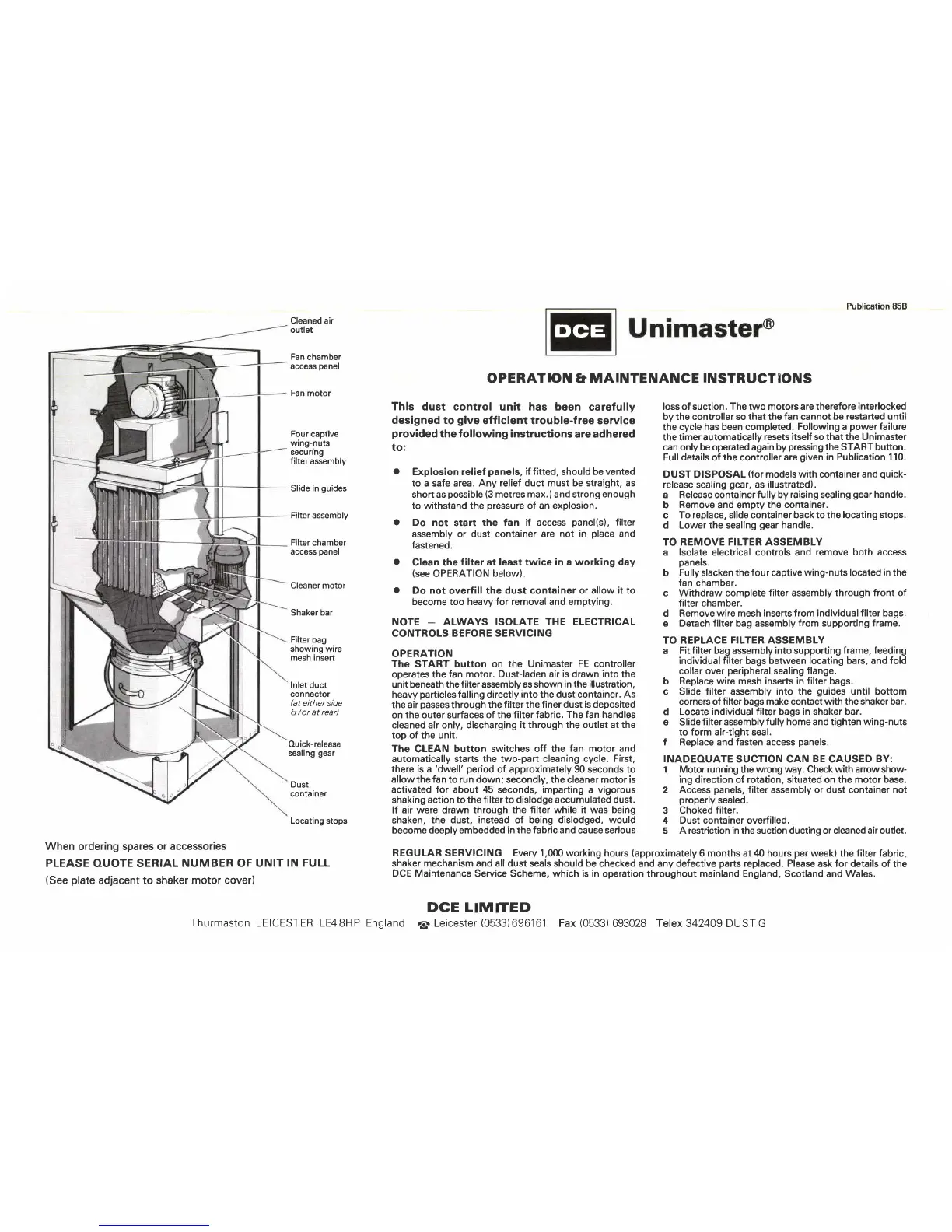
Cleaned air
outlet
Fan
chamber
access
panel
Fan
motor
Four captive
wing-nuts
secunng
filter
assembly
Slide
in
guides
Filter assembly
Filter chamber
access
panel
Cleaner motor
Shaker bar
Filter bag
showing wire
mesh insert
lnlet
duct
connector
bt either side
I /or at rear)
Ouick-release
sealing
gear
Dust
container
Locating
stops
When ordering spares or
accessories
PLEASE
OUOTE SERIAL
NUMBER OF UNIT
IN FULL
(See
plate
adjacent
to shaker motor cover)
DCE
This
dust control unit has been
carefully
designed to
give
efficient trouble-free service
provided
the following instructions
are adhered
to:
a
Explosion relief
panels,
if fitted,
should
be vented
to a safe area, Any
relief duct must be straight, as
short as
possible
(3
metres
max.
)
and strong
enough
to withstand the
pressure
of an
explosion.
a
Do
not
start
the fan if access
panel(s),
filter
assembly or dust container are
not in
place
and
fastened.
a
Clean the
filter at least twice in a working day
(see
OPERATION
below).
a
Do not overfill the
dust container or allow it to
become too heavy for removal and emptying.
NOTE
_
ALWAYS ISOLATE
THE ELECTRICAL
CONTROLS BEFORE SERVICING
OPERATION
The START button on
the
Unimaster
FE controller
operates the
fan motor. Dust-laden air
is
drawn into
the
unit beneath the
filter assembly as shown in the
illustration,
heavy
particles
falling directly
into
the dust container.
As
the air
passes
through the
filter the finer dust is deposited
on
the
outer surfaces
of the filter fabric.
The fan handles
cleaned air only, discharging
it through the outlet at the
top of the unit.
The
CLEAN
button switches off the
fan motor and
automatically starts the two-part
cleaning cycle. First,
there is
a
'dwell' period
of approximately 90 seconds to
allow the fan
to
run down;
secondly, the cleaner motor is
activated for about 45 seconds, imparting
a
vigorous
shaking action to
the filter to dislodge accumulated dust.
lf air were drawn through
the filter while it was being
shaken,
the dust, instead of being dislodged, would
become deeply embedded in the
fabric
and cause serious
@
OPERAT ON
ET
MA NTENANCE NSTRUCT
ONS
loss of suction. The two motors are therefore
interlocked
by the controller so that the
fan
cannot
be restarted until
the
cycle has been completed. Following a
power
failure
the timer automatically
resets itself so that the Unimaster
can only be operated again by
pressing
the START
button.
Full
details
of
the
controller
are
given
in Publication
110.
DUST DISPOSAL
(for
models with container and
quick-
release sealing
gear,
as illustrated).
a Release container f ully by
raising
sealing
gear
handle.
b
Remove
and empty
the container.
c
To replace, slide container back to the
locating stops.
d Lower the sealing
gear
handle.
TO REMOVE FILTER ASSEMBLY
a lsolate electrical controls and
remove both access
panels.
b
Fully
slacken
the four
captive
wing-nuts located in the
fan chamber.
c Withdraw complete
filter
assembly
through front of
filter chamber.
d Remove wire mesh
inserts from individual filter bags.
e Detach filter bag assembly from supporting
frame.
TO REPLACE
FILTER
ASSEMBLY
a
Fit filter bag assembly into supporting frame, feeding
individual
filter
bags between
locating bars, and fold
collar over
peripheral
sealing flange.
b Replace wire mesh inserts in filter bags.
c Slide
filter
assembly
into the
guides
until bottom
corners of filter bags make contact with the shaker bar.
d
Locate individual filter bags in shaker bar.
e Slide
filter
assembly
fully home and tighten wing-nuts
to form air-tight seal.
f Replace and fasten access
panels.
INADEOUATE
SUCTION CAN
BE
CAUSED
BY:
1
Motor
running
the wrong
way. Check with anow show-
ing direction of rotation, situated on the motor base.
2 Access
panels,
filter
assembly or
dust container not
properly
sealed.
3 Choked
filter.
4 Dust container overfilled.
5 A restriction in the suction ducting or cleaned air outlet.
REGULAR SERVICING Every 1,000
working hours
(approximately
6 months at
zl0
hours
per
week) the filter fabric,
shaker mechanism and all dust seals should be
checked and any defective
parts
replaced. Please ask for details
of the
DCE Maintenance Service Scheme, which is in
operation throughout mainland England,
Scotland
and Wales.
DCE L M TED
Thurmaston
LEICESTER LE48HP England
O,
Leicester
(0533)696161
Fax
(0533)
693028 Telex 342409 DUSTG
 Loading...