205
2 3
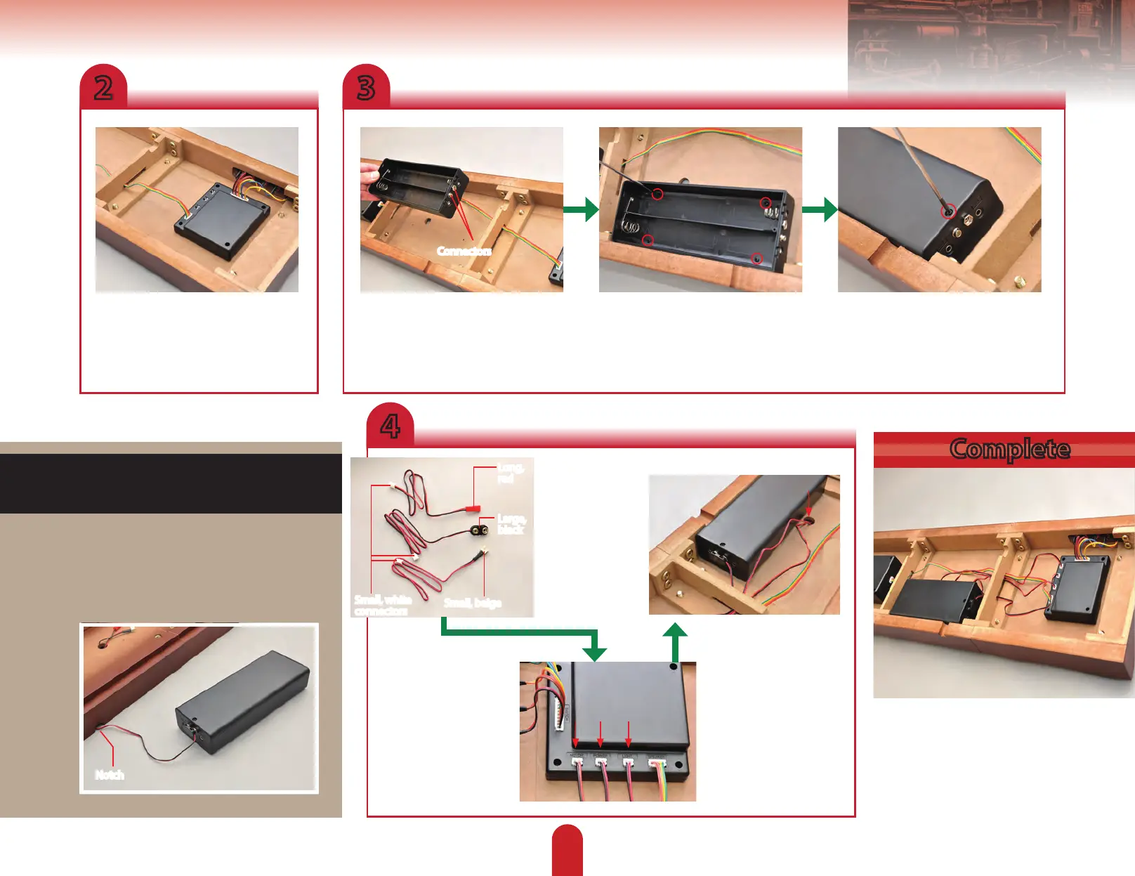
Take the wide connector leading from
the switches and t it into the socket
marked SWITCHES. Then take the
smaller connector leading from the
speaker and plug it into the socket
marked SPEAKER.
Now take Stage 89’s battery box and,
making sure its connectors are facing
towards the generator, lower it into
the base.
Fetch the 2.6 x 8mm screws from
Stage 89, and use them to ax the
battery box.
Now use the smaller-headed 2.3 x
8mm) screws from Stage 89 to secure
the lid.
Complete
4
Use the photo
to dierentiate
between the
three cables
supplied with
Stage 89. Top to
bottom, these are
the motor cable,
battery cable and
light cable.
Battery box position
The battery box is hidden on the underside
of the base, but if you’d rather have it
more readily accessible, you can leave it
unattached, with the wires tracing through
the notch indicated below.
Plug the small white
connectors of each into
their relevant, marked
sockets on the sound
eects generator.
Connectors
Small, white
connectors
Long,
red
Large,
black
Small, beige
Notch
Now feed the
cables’ other ends
through the slot
in the frame joint.
The battery cable’s
black connector
can be tted to the
connectors on the
battery box, while
the other two should
be fed through the
indicated hole in the
top of the base.
 Loading...