EasyManua.ls Logo

De Agostini Model Space C57 - User Manual

De Agostini Model Space C57
20 pages
Print Icon
To Next Page IconTo Next Page
Loading...
Build the
Steam
Locomotive
Pack 11
Question and Answer IconNeed help?

Do you have a question about the De Agostini Model Space C57 and is the answer not in the manual?

Summary

Detailing the tender 4

Your parts & Tools

Lists components and tools for the current assembly stage.

Step 1: Coupling Buffer Attachment

Attaching the coupling buffer to the rear of the tender.

The base 1

Your parts & Tools

Lists components and tools for the current assembly stage.

Step 1: Frame Alignment

Familiarizing and aligning frame parts for the base.

Steps 2-4: Base Frame Assembly

Assembling and securing the base frame using cap bolts.

The base 2

Your parts & Tools

Lists components and tools for the current assembly stage.

Step 1: Side Frame Identification

Identifying and preparing side frames C and D for assembly.

Steps 2-4: Base Frame Assembly

Assembling and securing the base frame using cap bolts.

The base 3

Your parts & Tools

Lists components and tools for the current assembly stage.

Step 1: Side Frame Identification

Identifying and preparing side frames E and F for assembly.

Steps 2-4: Base Frame Assembly

Assembling and securing the base frame using cap bolts.

The base top

Your parts & Tools

Lists components and tools for the current assembly stage.

Step 1: Top Plate Placement

Identifying and placing the base's top plates.

Steps 2-4: Top Plate Securing

Securing the base's top plates with cap bolts.

The speaker

Your parts & Tools

Lists components and tools for the current assembly stage.

Step 1: Speaker Protector Fitting

Placing the speaker protector onto the base.

Steps 2-4: Speaker Installation

Installing the speaker, cover, and connecting the cable.

The switchboard and battery box

Your parts & Tools

Lists components and tools for the current assembly stage.

Step 1: Washer Preparation

Preparing washers for the switchboard assembly.

Steps 2-4: Switchboard & Battery Box Assembly

Assembling switches and fitting the battery box.

The sound effects generator

Your parts & Tools

Lists components and tools for the current assembly stage.

Step 1: Generator Mounting

Mounting the sound effects generator onto the base.

Steps 2-4: Wiring and Battery Box Position

Connecting cables and positioning the battery box.

The track

Your parts & Tools

Lists components and tools for the current assembly stage.

Step 1: Ballast Placement

Placing ballast pieces onto the base for track construction.

Steps 2-4: Sleeper, Fastener, and Rail Fitting

Installing sleepers, rail fasteners, and rails.

Overview

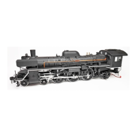
This document is a build manual for a model of the C57 Steam Locomotive, specifically Pack 11 of the De Agostini Model Space series. It guides the user through the assembly of various components of the model, focusing on detailing the tender, constructing the base in multiple stages, assembling the speaker, switchboard, battery box, sound effects generator, and the track.

Function Description:

The C57 Steam Locomotive model is a detailed replica designed for enthusiasts to build themselves. Once assembled, the model is intended to be a static display piece, featuring intricate details of the locomotive and its track. The inclusion of a speaker, switchboard, battery box, and sound effects generator suggests that the model will have interactive sound features, likely replicating the sounds of a steam locomotive, such as whistles and engine noises. The track components indicate that the locomotive will be displayed on a section of railway track, enhancing its realism as a display item.

Important Technical Specifications (as inferred from the manual):

  • Model Scale: Not explicitly stated, but implied to be a significant scale given the level of detail and the size of individual components.
  • Materials: Primarily wood for the base and track components, and plastic/metal for the locomotive and electronic parts.
  • Fasteners: Various screws (e.g., 2 x 4mm, 2.6 x 8mm, 2.3 x 8mm), cap bolts, and hex nuts are used for assembly.
  • Tools Required: Phillips screwdriver, hex wrench, synthetic rubber adhesive (SRA), tweezers, and pliers.
  • Electronic Components:
    • Speaker: Dual-driver speaker unit with a circuit board and protector.
    • Switchboard: Features switches for "MAIN," "RUN," "SOUND," "WHISTLE," and "LIGHT," indicating multiple interactive functions.
    • Battery Box: Powers the electronic functions.
    • Sound Effects Generator: Contains five sockets labeled "SWITCH," "MOTOR," "POWER," "LIGHT," and "SPEAKER," suggesting a central control unit for the model's electronic features.
    • Cables: Motor cable, battery cable, and light cable connect the electronic components.
  • Base Construction: Comprises multiple wooden frames (front end frame, side frames A, B, C, D, E, F, rear end frame, frame joints) and top plates (A, B, C, D). The base is designed to house the electronic components.
  • Track Construction: Includes ballasts (A, B, C, D), sleepers, rail fasteners, and long/short rails.

Usage Features:

  • Interactive Sound: The presence of a speaker and sound effects generator, controlled by a switchboard with "SOUND" and "WHISTLE" options, indicates that the model will produce locomotive sounds.
  • Lighting: A "LIGHT" switch on the switchboard suggests that the model will have functional lights, likely the locomotive's headlight.
  • Motor Function (Implied): A "MOTOR" socket on the sound effects generator and a "MOTOR" cable imply that there might be a motor component, though the manual focuses on static display elements. This could be for a subtle movement effect or simply a connection point for future stages.
  • Display Model: The detailed construction of the locomotive, tender, and track suggests its primary use as a high-quality display piece.

Maintenance Features (during assembly):

  • Adhesive Use: Synthetic rubber adhesive (SRA) is recommended for securing certain parts, such as the brake hose and overflow pipe on the tender, and optionally for washers on the switchboard. Instant adhesive is used to reinforce the brake hose.
  • Tightening Instructions: Specific instructions are given for tightening screws and cap bolts. For base construction, bolts are initially half-tightened or lightly tightened to allow for adjustment, then fully tightened later to ensure alignment.
  • Cable Management: Instructions are provided for feeding speaker and other cables through slots in the frame joints to keep them tidy and prevent trapping.
  • Component Orientation: Clear guidance is given on the correct orientation of parts, such as the coupling buffer, base frames, and top plates, to ensure proper assembly.
  • Pre-assembly Familiarization: The manual encourages users to familiarize themselves with parts before assembly, especially for components with subtle differences (e.g., side frames C and D, E and F).
  • Troubleshooting (Implied): The detailed, step-by-step instructions with clear images help prevent common assembly errors. For example, the warning about not trapping wires when lowering the speaker cover.

This manual is a comprehensive guide for assembling a complex and detailed model, emphasizing precision and careful construction to achieve a realistic and interactive replica of the C57 Steam Locomotive.

De Agostini Model Space C57 Specifications

General IconGeneral
BrandDe Agostini
ModelModel Space C57
CategoryToy
LanguageEnglish

Related product manuals