203
2
3
4
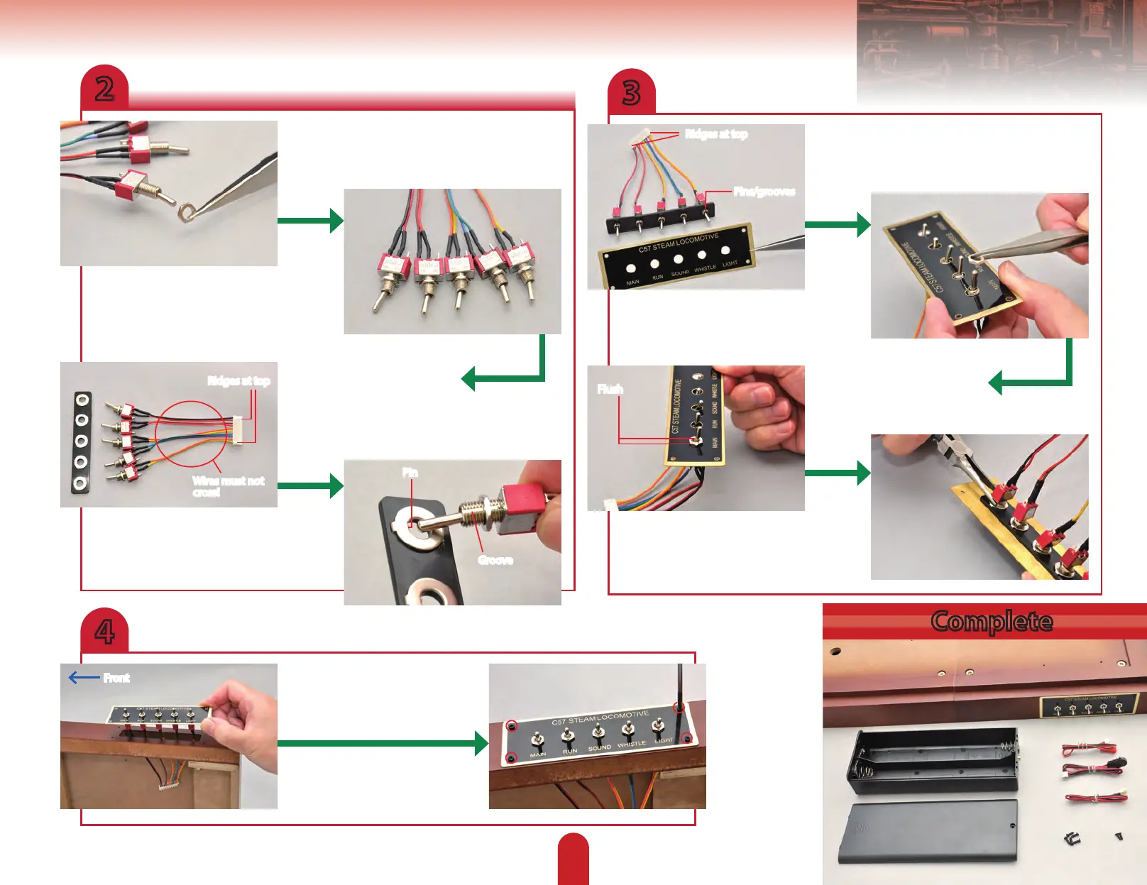
Fit a hex nut over each of the
switches.
Now line up the switches, with the
pin/groove side facing up, to the
switchplate, as shown.
Now t the switchplate to the
long rectangular hole in the
side of the base, as shown.
Use four of the smaller screws (2.3
x 8mm) to secure the plate.
Lay the switches out by the
switchboard, as shown – none
of the wires should cross. The
ridges on the connector block
should be positioned at the top.
Turn the hex nut until the end
of the threaded part of the
switch is ush with it.
Turn the nuts onto the threaded
part of the switches to about two
thirds of the way in.
Hold the parts together, then
place a hex nut onto the thread
of the rst switch.
Fit the switches into the washers, one by
one. The grooves through the threaded
section of the switches and the pin on
the washers will orient the parts.
Tighten the rear hex nut until the
switch is held securely in place. Then
repeat for the other four switches.
Complete
Ridges at top
Groove
Pin
Ridges at top
Wires must not
cross!
Pins/grooves
Flush
Front