L I V I 5 0 0
Operating instructions and warnings
9
andotherdataareprovidedinPoint4.2“TechnicalData”.
Satisfactoryoperationrequiresthecorrectpositioningofthe
LIVI500operatorwithrespecttothegate;DEASystemrecom-
mendedmeasurementsareshowninF5page32.
Theautomatismrequiredmustbeselectedaccordingtothe
gatetobemoved;theattritionontheattachments,theweight,
thelength/heightofthegatewing,andthedegreeofclosing
of the surfaces are the elements to be considered. The chart
“LENGTH-WEIGHT”correlatingthelengthofthegateleafand
itsweightintypicalsituationscanbeusedinselectingtheauto-
mationaccordingtothegatetobeautomated.
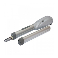
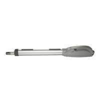
Wesuggesttousetherailarm(art.560B)withmodels501L
and503L.
WARNING Theuseoftheproductunderunusualconditions
notforeseenbythemanufacturercancreatesituationsofdan-
ger,andforthisreasonalltheconditionsprescribedinthese
instructionsmustberespected.
WARNING Under no circumstances must the product be
usedinexplosiveatmospheresorsurroundingsthatmayprove
corrosiveanddamagepartsoftheproduct.
4.5 Instructions for risk-free operation
4.5.1 Transport
The LIVI 500 gate operator is always delivered packed in
boxesthatguaranteetheproductadequateprotection.Carefully
readanywarningsorinstructionsforstorageandhandlingpro-
videdonthebox.
4.5.2 Installation,assemblyanddisassembly
Thefollowingoperationsareessentialtothecorrectlaying
oftheproduct:
• thecarefuldefinitionoftheentireautomaticopeninglayout
(seealso“6CompleteClosingAssembly”);inparticular,af-
tercarefullyassessingthecharacteristicsofthesupportsand
thegate,theattachmentsmustalsobedesignedandposi-
tionedaccordingtotheangleofopeningdesired(seeF2,F5
Page31e32);
• fastenthebracketandtheoperator(seeF6page33);
• assemblecarterandarm(seeF7andF8,page33);
• fasten the arm or the rail to the gate leaf by welding the
attachmentorwith4fixingscrews(notincluded).
WARNING Allinstallation,maintenance,cleaningorrepair
operationsonanypartofthesystemmustbeperformedexclu-
sively by qualified personnel with the power supply discon-
nectedworkinginstrictcompliancewiththeelectricalstandar-
dsandregulationsinforceinthenationofinstallation.
WARNING Toensurecompliancewithregulationsandsafe
operationofthe motor,werecommendtouseDEASystem
controlpanelsonly.
The fastening of the attachments must be performed with
extraattentiononbothironpillarsandmasonryworksandgates
ofanytype.
The necessity of installing reinforcement plates for iron
pillarsandgatesmustbecarefullyassessedwheneverthere-
mainingpartofthestructuredoesnotappearsufficientlystrong,
wheneverthemetalplateuseddoesnotappearthickenoughor
wheneverthemorphologyofthegateappearstolacksolidity.
To install the bracket on masonry posts use appropriate
screwanchors(mechanicalorchemicalfixing)notincluded.
Keepallweldingseamswellprotectedfromcorrosion.
Giveextraattentiontothealignmentoftheattachmentsand
theircorrectverticalpositioning.
4.5.3 Starting
Theinstallationoftheproductrequiresmasonryand/orwel-
dingandelectricalconnectionoperationsusingadequateequi-
pmentforthejobincompleterespectoftheaccident-prevention
standardsandregulationsinforceinthenationofinstallation.
Theproductmustbeelectricallyconnectedtoaspecialcon-
trolunitforgateoperators;seetheinstructionsprovidedforsuch
deviceforfurtherinformation.Whenusingart.502ENtogether
withcontrolpanelart.202RR,usethesuppliedadaptorcable
byinstallingitonthecontrolpanelandconnecttotheencoder
readerpayingattentiontoindicatedpolarityasshowninpicture
F12atpage34.
4.5.4 Use
Theproductisdestinedforincorporationintheassemblyof
devicesthatcomprisethegate’sautomatism.DEASystemassu-
mesthatitwillalwaysbeusedincompliancewiththestandards
andregulationsinforce.
“TROUBLE-SHOOTING” table
MALFUNCTION CAUSES / SOLUTIONS
When the opening command is given,
the gate wing fails to move and the
operator’s electric motor fails to start
The operator is not receiving correct power supply. Check all connections, fuses,
and the power supply cable conditions and replace or repair if necessary
When the opening command is given,
the motor starts but the gate wing fails
to move
Check that the unlocking system is closed (see F9, page 33)
Make sure that the electronic device for electric power adjustment is in good
condition
The operator jerks during movement
If the wing of the gate does not move freely, release the piston and readjust the
rotation points
The power of the gearmotor may be insufficient for the characteristics of the
gate’s wing; check the choice of model whenever requiredh
If the operator attachment to the gate bends or is badly fastened, repair and/or
buttress it.
“LENGTH-WEIGHT”chart
 Loading...