L I V I 5 0 0
Operating instructions and warnings
10
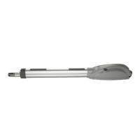
AllLIVI500modelshaveanunlockingsystem;theworking
ofthissysteminthe502and503seriesisthefollowing:after
unlockingthelockonthehandle(protectedbyaplasticcover)
turntheleverinthedirectionshowninF9,page33;theoperator
isnowunlockedand,ifnoobstructionshinderitsmovement,the
gatecannowmovefreely.Theoppositeprocedure,thatisthe
rotationoftheleveruptothelimitswitchandthelockingofthe
lock(remembertoprotectthelockwiththeappropriatecover)
returnsLIVI500toitsnormalworkingconditions.
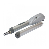
InLIVI500and501theunlockingsystemcanbeoperated
asfollows:afterunlockingthelockon the case (protected by
aplasticcover)removethecaseandturntheleveronposition
2(seeF9,page33);theoperatorisnowunlockedand,ifno
obstructionshinderitsmovement,thegatecannowmovefre-
ely.Theoppositeprocedure,thatistherotationoftheleverto
position1andtheassemblingofthecaseandlockingsystem
(remembertoprotectthelockwiththeappropriatecover)returns
LIVI500toitsnormalworkingconditions.
If,forwhateverreason,thereleaseunitisinaccessible,you
caninstallonallmodelstheaccessory560M“Releasedevice
withcable”(see “PRODUCT ACCESSORIES”)by following the
instructionsenclosedtherein.
4.5.5 Adjustment
Theinstallationofseries500and502productsdoesnotrequi-
readjustments;theonlyadjustmentrequiredfortheinstallationof
series501and503productsisthepositioningofthestroke-end.
You can make such adjustments by unscrewing the fixing
screwsofthelimitswitchcheckcamsandthelimitswitchcams
(seeF3,page31),byrotatingthelatteralongthecamholder
uptothechosenpositionandbyscrewingonthescrewsagain.
WARNING Alltheotheradjustment/settingoperationsbeyond
theadjustmentoftheoilflowaremadebythemanufacturer.
Tamperingwiththesesettingsmaycausemalfunctionand/or
situationsofrisktopeople,animalsandproperty.Refrainfrom
performinganyoperationsnotauthorisedbyDEASystem.
4.5.6 Maintenanceandrepair
Goodpreventivemaintenanceandregularinspectionensure
longworkinglife(seealso“Warranty”).Consultthe“TROUBLE-
SHOOTING”table(seepage9)wheneveranomaliesareobser-
vedinordertofindthesolutiontotheproblemandcontactDEA
Systemdirectlywheneverthesolutionrequiredisnotprovided.
Theinspection/maintenanceoperationstoberoutinelysche-
duledinthe“completeautomatismmaintenanceregister”are:
INTERVENTION TYPE PERIODICITY
cleaning of external surfaces 6 months
checking of screw tightening 6 months
checking of release
mechanism operation
6 months
greasing of articulated joint 1 year
WARNING Allinstallation,maintenance,cleaningorrepair
operationsonanypartofthesystemmustbeperformedexclu-
sivelybyqualifiedpersonnelwiththepowersupplydisconnec-
ted workinginstrictcompliancewith theelectricalstandards
andregulationsinforceinthenationofinstallation.
WARNING TheuseofsparepartsnotindicatedbyDEASy-
stemand/orincorrectre-assemblycancauserisktopeople,
animalsandpropertyandalsodamagetheproduct.Forthis
reason,alwaysuseonlythepartsindicated byDEASystem
andscrupulouslyfollowallassemblyinstructions.
4.6 Training
Afterinstallationandsetting,thecorrectoperationofthecom-
pleteautomatismmustbecarefullyillustratedtothefinaluser.
TheLIVI 500 gate operatorrequires careful instructionon
thereleasemechanism(see“Enclosures”)inparticularandthe
respectivemaintenanceschedule(seePoint4.5.6.).
WARNING AwarenessoftheoperationoftheLIVI500key-
releasemechanism(seeF9Page33)isessentialforallusers
oftheautomatismbecausethefailuretousethedevicequic-
klyduringemergenciescanjeopardisepeople,animalsand
property.EnclosureItotheseinstructions,whichtheinstaller
isrequiredtodelivertothefinaluser,illustratesoperationand
canbedetached.
4.7 Inappropriate use
Chapter“4.4Appropriateconditionsofuse”describesthe
conditionsforwhichtheproducthasbeendesignedandtested.
Theproductmustneverbeusedforotherpurposes.
WARNING Theuseoftheproductunderunusualconditions
notforeseenbythemanufacturercancreatesituationsofdan-
ger,andforthisreasonalltheconditionsprescribedinthese
instructionsmustberespected.
WARNING Under no circumstances must the product be
usedinexplosiveatmospheresorsurroundingsthatmayprove
corrosiveanddamagepartsoftheproduct.
5 SPARE PARTS LIST
Thelistofsparepartsthatcanbeordered(Pages28,29)is
adetailedlistthataccompaniestheexplodedviewoftheproduct
andmustbeusedtoorderspareparts.
Thefollowingdatamustalwaysbeprovidedwhenordering
spareparts:
• thecodeoftheproduct(seenontheproductlabel;seeF4,
Page32),
• thepart’spositionnumberintheexplodedview,
• ifavailable,theproduct’s purchasedatemaybeusefulin
somecases.
6 COMPLETE CLOSING ASSEMBLY
Thischapterillustratesthetypicalinstallationofacomple-
teautomatism for the purposeof informing and assistingthe
installerintheselectionofthevariouspartstobeusedincom-
pliancewithMachineryDirective(2006/42/CE)andEuropean
SafetyStandards(EN14453-EN12445)forgateinstallation.
Thedataprovidedinthischapterareneithercompletenor
exhaustive,andDEASystemdeclinesallliabilityforanyerrors,
omissionsorinaccuraciesthatmayoccur.
6.1 Minimum level of protection provided by the
safety edge
Amongthemostseriousriskstobeconsideredfortheauto-
mationofaswinggateistheriskofcrushingbetweentwowings
orbetweenonewing and its stop duringclosing.Regulations
prescribetheadoptionofoneofthefollowingtypesofcontrols
againstsuchrisksdependingontheuseforeseenforthegate.
An appropriate type of operating control board must be
usedaccordingtothegatetypeanduseagainstsuchrisk,as
providedforbythequotedregulations(see“OPERATINGCON-
TROL”table).
6.2 Crushing in the opening area
Theriskofcrushingcanalsoariseintheareabetweenthe
gatebeingopened and thewallorotherconstructionbehind
it. F10 on Page 33 provides the measurements that must be
respectedwhenevermeasuresarenottakentolimittheimpact
forceorwheneverpresencedetectionsystemsarenotused.
6.3 Impact in the opening/closing area
Inordertoavoidcrushingbythegatewingintheclosing
area,installapairofphotocells(A)(recommendedheight:500
 Loading...