9
2 PRODUCT DESCRIPTION
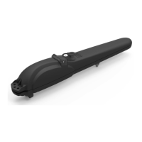
Models and contents of the package
MAC/STING identies a family of operators with different characteristics as regards the supply voltage, the reversibility and the pre-
sence of the encoder.
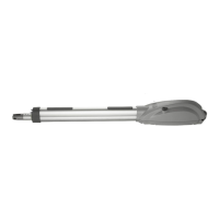
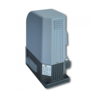
MAC/STING is designed for installation in residential swing gates, is composed primarily of a mechanical gear motor that drives the
lead screw fastened to the front attachment by means of the adjustment screw.
MAC/STING is completed by a set of accessories listed in the “PRODUCT ACCESSORIES” table (page 55).
Inspect the “Contents of the Package” (Pic. 1) and compare it with your product for useful consultation during assembly.
Transport
MAC/STING is always delivered packed in boxes that provide adequate protection to the product, however, pay attention to all infor-
mation that may be provided on the same box for storage and handling.
3 TECHNICAL DATA
MAC - STING
MAC/EN
STING/EN
MAC/R
MAC/24 - MAC24/EN -
STING/24
MAC/24/E
Motor power supply voltage (V) 230 V ~ ±10% (50/60 Hz) 24 V
Absorbed power (W) 300 60 50
Max Thrust (N) 1650 1200 1000 500
Duty cycle (cycles/hour) 18 22 18 40 10
Maximum n° of operations in 24 hour 90 90 45
Built-in capacitor (µF) 8 10 /
Operating temperature range (°C) -20÷50 °C
Motor thermal protection (°C) 150 /
Opening time 90° (s) 16 11,5
Weight of product with package (kg) 8,8
Protection degree IPX4
4 INSTALLATION AND ASSEMBLY
4.1 For a satisfactory installation of the product is important to:
• Verify that the gate complies with the legal requirements and then dene the complete project of the installation;
• Verify that the gate is well balanced and that it has no points of friction in opening and closing;
• Identify an area that allows a smooth and safe manual operation of the operator;
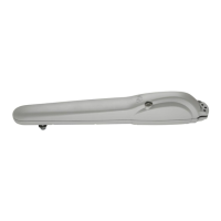
• Verify that the operator bulk (Pic. 2) is compatible with the area chosen for the tting (Pic. 3);
• Use the length/weight graphic and the provided installations dimensions evaluating whether you prefer a 90° or higher opening (Pic.
4).
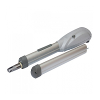
4.2 Dened and satised these prerequisites, proceed to the assembly:
• Fix the rear junction to the pillar bu welding (Pic. 5);
• Fix the front junction to the gate by welding (Pic. 6);
• Keeping the motor in a horizontal position, mount it rst to the front bracket, then to the rear bracket (Pic. 7) ensuring that installation
dimensions shown in Picture 4 are respected.
WARNING In order to make the structure sufciently strong, reinforcement plates to be xed to attachments may be necessary.
WARNING Grease pins before assembly.