Do you have a question about the Dean RWA Series and is the answer not in the manual?
Initial checks and quality control procedures before pump installation.
Guidelines for receiving, handling, and storing the pump prior to installation.
Critical safety precautions applicable to all phases of pump operation and maintenance.
Details on the materials used for various pump components across different models.
Steps for preparing the foundation and securely mounting the pump baseplate.
Advice on selecting and reapplying pumps for specific service conditions.
Best practices for connecting suction and discharge piping to the pump.
Detailed instructions for achieving precise alignment between pump and driver shafts.
Maximum forces and moments permitted on pump flanges to prevent damage.
Information on pump bearings, lubrication methods, and mechanical seal functionality.
Step-by-step process for filling the pump with liquid and initiating operation.
Essential warnings and procedures to ensure safe and efficient pump operation.
Instructions for ordering replacement parts, including necessary information.
Visual diagrams illustrating pump components and their assembly for reference.
Critical safety measures required before and during pump disassembly to prevent injury.
Detailed, sequential instructions for dismantling individual pump components.
Specific guidance on the removal and handling of pump bearings and seals.
Step-by-step process for correctly installing the mechanical seal and associated gland.
Instructions for reassembling the pump's fan and coupling components.
Procedures for final checks, including torque specifications, after reassembly.
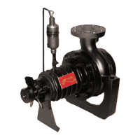
This document describes the CECO Dean Series RWA Fan Cooled Hot Water Pumps, providing comprehensive instructions for their installation, operation, and maintenance. These pumps are specifically designed for use with hot water, ethylene glycol, propylene glycol, and triethylene glycol, and are not suitable for other liquids.
The CECO Dean Series RWA pumps are fan-cooled, horizontal, single-stage, end-suction, enclosed impeller, centrifugal pumps. Their primary function is to circulate hot water and specific glycol solutions within a system. The fan-cooled design helps manage the temperature of the pump, particularly in hot water applications. The mechanical face seal, a critical component, is specifically selected for sealing hot water and glycol solutions, ensuring that the seal faces are continuously lubricated by the pumped liquid. A vapor eliminator, mounted on top of the pump, removes any vapor that may form at the seal faces during operation, preventing potential issues. The pump's design incorporates a radial bearing lubricated by the pumped liquid, eliminating the need for external lubrication for this component. The thrust bearings, however, are grease-packed "for life" and require no further lubrication until the pump is rebuilt.
Before installation, users must thoroughly read and understand the entire instruction manual, along with any relevant Material Safety Data Sheets (MSDS) for the fluids being handled. Proper application and reapplication are crucial; users must verify that the pump's serial number matches the intended service and that its construction materials, sizing, sealing, pressure, head, and temperature capabilities are appropriate for the specific service conditions.
The pump requires a rigid foundation to prevent vibration and distortion, and the baseplate must be properly set, leveled, and secured. Suction and discharge piping must be independently supported to prevent strain on the pump, and thermal expansion joints should be used to guard against expansion loads. Piping should be as short and straight as possible, with diameters determined by system requirements. Strainers or filters are recommended in the suction line to prevent debris from damaging internal pump parts, bearings, and mechanical seals.
Crucially, the pump and driver alignment must be checked and corrected before grouting the baseplate, and again before the pump is first started. This alignment must also be rechecked at operating temperatures. Misalignment can lead to vibration, reduced bearing life, and mechanical seal failure. The coupling spacer should be removed for initial alignment and motor rotation checks.
When starting the pump, it is essential to prevent thermal or pressure shock by allowing the liquid to flow into the casing slowly. The pump must never be started until all parts are at the temperature of the liquid being pumped. Before filling, all leak locations must be sealed, and the pumpage leak detection connection must remain open. The pump must be filled by venting air to the atmosphere, either through an exhauster, a foot valve, or a bleed-off line, depending on the system configuration and liquid source. The seal cavity must also be filled with liquid to lubricate the mechanical seal faces.
A critical step before full operation is checking the direction of rotation. Incorrect rotation can cause extensive damage. The pump should never be operated at shut-off (no flow) or at low flow conditions, as this can lead to dangerous heat buildup, high pressure, and potential rupture of pressure-containing parts. The pump must also never be run without liquid in the casing, as this can cause extensive damage to bearings and mechanical seals. After initial operation, the bearing grease relief plug (for RWA4166 and RWA4206 models) should be reinstalled and tightened.
Regular maintenance is essential for the longevity and safe operation of the CECO Dean Series RWA pumps. The manual outlines detailed disassembly and reassembly procedures, emphasizing that all work must be performed by thoroughly trained and qualified personnel. Safety precautions, including wearing appropriate protective apparel and using mechanical lifting equipment, are paramount during any maintenance task.
Before opening the pump or system, all fluids must be drained from auxiliary sub-systems and the pump itself into separate containers. Each fluid should be handled with caution, referencing its MSDS. The system should then be flushed with a compatible, non-toxic, non-hazardous, stable liquid to reduce exposure risks. Any remaining pressure in the pump must be carefully bled off through a valved drain line to a closed container. Extreme caution is advised when opening the pump, as isolation valves may not be sealing, or solid pumpage may be blocking the drain.
During disassembly, the coupling guard and coupling spacer must be removed. Care must be taken not to bend the fan blades. The bearing housing foot, casing capscrews/nuts, and mechanical seal gland components are systematically removed. The mechanical seal stationary seat and rotary components, along with the grease seals, are removed, often requiring specific tools or techniques to prevent damage. The thrust bearings are pressed off the shaft, and the bearing cartridge is pressed out of the bearing housing.
For reassembly, all parts must be thoroughly cleaned, inspected, and replaced if worn, corroded, eroded, or otherwise deteriorated. Only Dean Pump Division parts should be used. The shaft should be inspected for wear patterns under the lip seal and bearing. A new bearing cartridge is pressed into the bearing housing, ensuring correct orientation for different pump models. Thrust bearings are pressed onto the pump shaft, with specific instructions for angular-contact types to ensure back-to-back assembly. The bearing lock nut and washer are installed and secured for RWA4166 and RWA4206 models.
Thrust bearings for RWA4166 and RWA4206 models require specific grease packing, with precise quantities indicated. New grease seals are pressed into the mechanical seal gland, with the lip pointing towards the impeller end. New seal gland gaskets are installed and lubricated with a rubber lubricant emulsion. The mechanical seal stationary seat is installed into the gland, ensuring the "O" ring is properly seated and the polished face is away from the lip seal. For RWA4206, the slot in the stationary seat must align with the anti-rotation pin.
The mechanical seal rotary is carefully slid onto the shaft sleeve (for RWA4166/RWA4206) or pump shaft (for RWA2096), lubricated, and its set screws tightened. The shaft assembly, including the mechanical seal gland and thrust bearings, is then carefully slid into the bearing housing. For RWA4166 and RWA4206, a new end cover gasket and lip seal are installed, and the end cover is bolted securely to the bearing housing.
The fan collar, fan, and fan clamp ring are installed on the pump shaft, with specific measurements and orientations for different RWA models. The coupling hub is then installed, ensuring it is flush with the end of the pump shaft, and the key is properly seated. The impeller key and impeller are slid onto the pump shaft, followed by the impeller washer and nuts/bolt, tightened to specified torque values. If present, the casing ring is pressed into the casing.
Finally, the bearing housing assembly is carefully inserted into the casing with a new casing gasket, ensuring full contact with the baseplate. Casing cap screws or stud nuts are tightened slowly and evenly to compress the gasket. The pump shaft should be rotated by hand to check for interference. If the casing was removed, it is reattached to the baseplate, and suction and discharge flanges are reconnected with new gaskets. The bearing housing foot is bolted to the baseplate, and the pump shaft is rotated again to check for rubbing. Re-alignment of the pump and driver is performed, and the pump is lubricated, started, and checked according to the start-up checklist. The vapor eliminator and exhaust tube are reinstalled after filling and venting the seal chamber.
| Series | RWA |
|---|---|
| Power Source | Electric |
| Flow Rate | Varies by model |
| Maximum Head | Varies by model |
| Inlet Size | Varies by model |
| Outlet Size | Varies by model |
| Motor Power | Varies by model |
| Voltage | Varies by model |
| Material | Cast Iron |
| Weight | Varies by model |