EasyManua.ls Logo

Deca D-MIG500 - Maintenance

Default Icon
Print Icon
To Next Page IconTo Next Page
To Previous Page IconTo Previous Page
Loading...
950568-03 22/08/16
4) Burn back


5) Soft start


6) Thermal cutout signal

Xthermal cutout




Recommendations for use







L 


Maintenance


Ordinary maintenance 
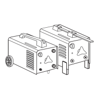




Fig.10



Extraordinary maintenance          





FR
Manuel d’instruction

           

           ,

     
  


IEC ou CLC/TS 62081.
Avertissements de sécurité
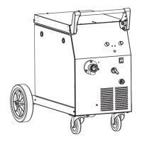




            









  



             

 

Fig.3
Starting up






Assembly and electrical connections
¾ Fig. 8.
¾ 

 Fig. 4,1.
L            



¾ Plug(2P+T for 1Ph
and 3P+T for 3Ph)Fig.4,2.
¾ 
Fig. 5
L 
Preparing the welding circuit
¾ 

¾ Connect the torch
L 
Fig. 4,3.
Installing the continuous wire
Fig. 6
Fig.
6,5,a, the contact tip Fig. 6,9,b

L Fig. 6,5,c





L 


Installing the protective gas cylinder** and pressure reducer**



Fig. 7
Gas Application
 

2 
2 
CO2 
L 
L 

** (This component may not be included with some models).
Welding process: description of controls and signals


Fig. 1
1) Adjusting the welding current


L              

2) Adjusting the wire speed
     
Fig.4,4



3) Welding timer




Related product manuals