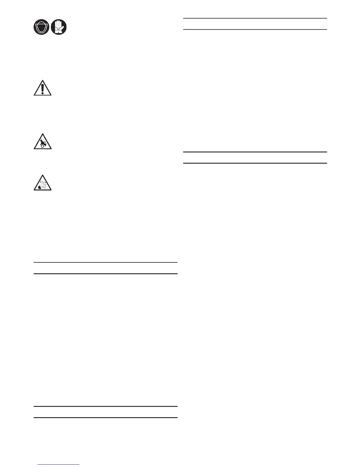
EasyManua.ls Logo

Deca sm 1270 - English Manual: Connections and Programs; Battery Charger Connection Procedure; Charging Program Selection; Technical Data

Deca sm 1270
Print Icon
To Next Page IconTo Next Page
To Previous Page IconTo Previous Page
Loading...
950519-07 23/09/15
A

N
P   

N     

Additional warnings
N
N

P


Warnings for batteries in vehicles




Warnings for batteries in vehicles
N






I



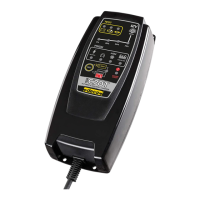
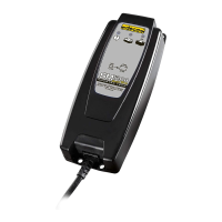
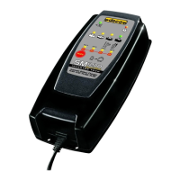
Battery charger description
      
        


L     

Control and signal LEDs - FIG 1
 
 
 
 
 
 
 
 

 
 

 
Technical data
 
 
 
 

Battery charger connection
¾ 

¾ 
¾ 

¾ 
L “C”

connection.
¾ 

¾ 

L “B”

L       


Charging program selection

P1) 14.4 Volt charging


P2) 14.7 Volt charging


       

        
FIG 2
PHASE 1
         
“D”


“C”

PHASE 2
        
          
“E”

PHASE 3
    
“F”
L       

    “C”  


PHASE 4
         
“G”

         

       

PHASE 5



Related product manuals