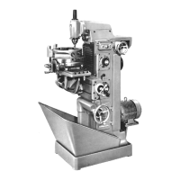
Maschine und Zubehőr 3. Universaltisch
Machine and attachments 3. Universal tabie
Hauptteile und Bedienungs-Elemente
(a)
(Ь)
(c)
(d)
(e)
(f)
(9)
(h)
(і)
(k)
(1)
(m)
(n)
K1emm-Muttern (Drehen Achse C)
(siehe Seíte 7-10)
Fűhluhr für Tísch-Eínstellung Achse B
(siehe Seite 7-11)
Fűhluhr fűr Tísch-Eínstellung Achse A
(siehe Seite 7-11)
Wínkel-Ska1a (Achse B)
(siehe Seite 7-9)
Spindel zum Schwenken
um Achse B(siehe Seite 7-8)
K1emm-Schrauben (Kíppen Achse A)
(siehe Seite 7-7)
K1emm-HeЬe1 fűr Tisch-Klemmung
(siehe Seite 7-5)
Winkel-Ska1a (Achse A)
(siehe Seite 7-7)
Fűhluhr für Tísch-Eínstellung Achse C
(siehe Seite 7-11)
Stellknopf fűr Wahlder Untersetzungs-
stufen (siehe Seíte 7-12)
Handrad zum Drehen der Tisch-Platte
um Achse C(siehe Seíte 7-10)
Spindel zum Kippen um
Achse A (siehe Seite 7-7)
K1emm-Schrauben (Schwenken Achse B)
(siehe Seite 7-8)
Der Universaltisch wird mit dígítaler Po-
sitions-Anzeige geliefert.
Technísche Daten
Bestell-Nr. ....... 2038 001200
... 430 mm x 710 mm
........ 7
. . . . . . . 14H7mm
.. . . . . . 63 mm
Mittelbohrung (ø/Tiefe) ... 63 H618
Abstand Tischmitte/
Anschraubfläche ...
Max. Durchgangshőhe
Senkrecht-Frässpíndel/
Tíschfläche .....
Zulässíge Belastung ..
Gewi cht . . . . . . . .
Dreh-Bereich Achse C
bei waagrechter Stellung
Kipp-Bereich Achse A
zur Maschine .....
von der Maschine ...
Schwenk-Bereich Achse B .
Meβ-Bereích bei Digital-Anzeige
direkt .. Auflősung 360.000 x 0.0010
Untersetzungs-
verhältnísse .. 60:1/120:1/240:1
Auf spannf 1 äche .
T-Nuten Anzahl .
Breite .
Abstand
260 mm
387 mm
300 kg
230 kg
3600
450
150
+ 450
Maín assemblíes and controls
(a) Clamping nuts (table rotation about
C axis) (p 7-10)
(b) Dia1 indicator (table fine adjust-
ment in B axis) (p 7-11)
(c) Dia1 indicator (table fine adjust-
ment in A axis) (p 7-11)
(d) Tab1e setting scale (B axís)
(p 7-9)
(e) Lead screw for pivoting table about
B axís (p 7-8)
(f) Clamping screws for tiltíng table
about A axís (p 7-7)
(g) Tab1e clamping lever (p 7-5)
(h) Tab1e setting scale (A axis)
(p 7-7)
Día1 indicator (table fine adjust-
ment in C axís) (p 7-11)
Control knob for setting reduction
ratio (p 7-12)
Handwheel for table rotation about
C axís (p 7-10)
Lead screw for tilting table about
A axis (p 7-7)
(n) Clamping screws for pivoting table
about B axís (p 7-8)
The universal table is supplied with
digítal position readout.
(í)
(k)
(1)
(m)
Technical data
Stock No ................... 2238 001200
Clamping surface .......... 710 x 430 mm
(28" x 17")
7 T-slots, width ...... 14 mm H7 (9/16")
spaced ................ 63 mm (2 1/2")
Centre recess dia .... 63 mm H6 (2 1/2")
depth ................... 8 mm (5/16")
Distance, table centre/
mounting surface ........ 260 mm (10")
Max clearance, vertical
spindle/table surface ... 387 mm (15")
Max table load approx .. 300 kg (660 1b)
Weight ...... .... ... 230 kg (510 1Ь)
Swivel range (C axís), table
in horizontal position .......... 360°
Tilting range (A axís)
towards/away from machine .... 45°/15°
Pivoting range (B axís), both ways 45°
Measuring range, digital position
readout (direct),
resolution .......... 360 000 x 0.0010
Reduction ratios ...... 60:1/120:1/240:1
It should be noted that non-metric
va ues are approxımatıons.
1-11
 Loading...