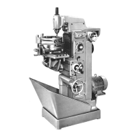
Maschíne und Zubehör 7. Teilkopf
Machine and attachments 7. lndex head
Hauptteíle und Bedíenungs-Elemente
(a) Knebel (Klemmung Teilkopf-Spíndel)
(siehe Seite 7-71)
(Ь) Knebel zur Klemmung der Tei1-Einrich-
tung (siehe Seíte 7-70)
(c) Winkel-Ska1a (siehe Seite 7-73)
(d) K1emm-Schraube (siehe Seíte 7-75)
(e) Loch-Scheibe (siehe Seite 7-81)
(f) Hand-Kurbel mit Tei1-Einrichtung
(siehe Seite 7-73 bís 7-80)
(g) Reitstock
(siehe Seíte 7-69 und 7-80)
(h) Gegenhalter (siehe Seite 7-69)
(í) Justier-Stíft (siehe Seíte 7-72)
(j) Rasten-Scheibe (siehe Seite 7-71)
Der Tei 1 kopf wi rd mi t Gegenhal ter und Rei t-
stock geliefert.
Im Zubehör befindet sich die Anzugstange
für die Spannzangen.
Technísche Daten
Bestell-Nr. ....... 2212 000750
Spíndel-Innenkegel ....... SK 40
Spannzangenbohrung bis .... 25 mm
Durchgangsbohrung ...... 25 mm
Spi tzenhöhe über Auf spannf 1 äche . 90 mm
Spitzenhöhe bis Gegenhalter .. 100 mm
Abstand Spann-Achse/
Anschraubfläche ....... 91 mm
Schwenk-Bereich Achse B ..... + 900
Kipp-Bereich Achse A
von der Maschine ........ 60
zur Maschi ne . . . . . . . . . . 150
Skalenwert für
Schwenk- und Kippbewegung ... 10
Direkte Teilung nach
Teilkreís-Ska1a ....... 3600
Skalenwert .......... 10
Teilung mit Rasten, Anzahl .... 24
Indirekte Teilung mittels Schneckentrieb
nach Skalen- oder Lochscheibe
Skalenwert am Schneckentrieb .. 1'
Schneckentrieb-Untersetzung .. 40:1
Lochkreise für Indirekt-Teilung
(3 Scheiben)
27,31,34,41,43/
33,38,39,42,46/
36,37,40,58
Teílungsfehler max.
beí direkter Teilung ..... 1'30"
beí índírekter Teílung ..... 1'
Gewicht
mít/ohne Gegenhalter ... 64/41 kg
Maín assemblíes and controls
(a)
(Ь)
(c)
(d)
(e)
(f)
(g)
(h)
(í)
(j)
Clamping lever (index spindle)
(p 7-71)
Clamping lever (indexing unit)
(p 7-70)
Angular setting scale (p 7-73)
Clamping screw (p 7-75)
Perforated index plate (p 7-81)
Hand crank with indexing unit
(p 7-73 to 7-80)
Tailstock (p 7-69 and 7-80)
Overarm (p 7-69)
Index pin (p 7-72)
24-register index plate (p 7-71)
The index head is supplied with an over-
arm and tailstock.
The range of accessories includes a
drawbar for collets.
Technícal data
Stock No ................... 2212 000750
Index spindle taper .............. ST 40
Co11et capacity ............. 25 mm (1").
Through bore dia ............ 25 mm (111)
Centre height above
clamping surface ...... 90 mm (3 1/2")
up to overarm ............ 100 mm (4"),
Distance, clamping axis/
mounting surface ...... 91 mm (3 1/2")
Swivel range (B axís) ............. 360°
Tílting range (A axis)
towards/away from machine ..... 15°/6°
Sca1e divisions for pivoting
and tilting motions ............... 1°
Direct indexing by 360° scale,
1 division ........................ 1°
Direct indexing, registers .......... 24
Indirect indexing via worm gearing
by scale or index plates, divisions
on worm gearing scale ... 1 min of arc
Worm gear reduction ratio ......... 1:90
InЈex'circles for indirect
í)ıdexing (3 perforated index plates)
27, 31, 34, 41, 43/
33, 38, 39, 42, 46/
36, 37, 40, 58
Max indexing error,
direct indexing ............ ,.. 1 30"
indirect indexing ....... 1 min of arc
Weight with overarm ..... 64 kg (140 1Ь)
without overarm ........ 41 kg (90 1Ь)
It should Ьe noted that non-metгε
va ues are approximations.
1-19
 Loading...