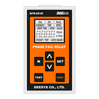
DFR-021D Phase Fail Relay
The DFR-021D is a single open-phase detector designed to identify and alarm open phases or load unbalance within a three-phase circuit. It achieves this by monitoring the current in the normal operating state. The device utilizes the MCT-A31 as an input converter to measure and detect the three-phase load current. The MCT-A31 takes the secondary current of the Main CT as its input, with an I/O current ratio of 3,000:1.
Technical Specifications
DFR-021D:
- Control Power: AC/DC 100 to 240V, 50/60Hz, < 3VA
- Rated Input: AC 1 to 160A (primary current of MCT), 3Phase, 50/60Hz
- Reference Current Setting: 1.0 to 10.0A (0.1 step)
- Unbalance Rate Setting: 10 to 90% (1 step)
- Start-Lock Time Setting: 1.0 to 60.0sec (0.5 step)
- Alarm Operation Time Setting: 1.0 to 60.0sec (0.5 step)
- CT Ratio Setting: 5 to 1,000A (5 step)
- Alarm Reset Setting: Auto / Manu
- Output Pulse Action Mode: Pulse / Latch
- Pulse Retention Time: 0.1 to 10.0sec (0.1 step)
- Motion Precision: ± 10% at setting value
- Motion Indication: LCD blinking red
- Insulation Resistance: More than 100M Ω with DC 500V Megger
- Insulation Strength: 2,000V AC rms 1 minute
- Surge / Impulse: IEC255-4: 5kV (1.2X50 μs) / IEC255-22-1: 2.5kV (1MHz)
- Case Material: LUPOY (Black Color) resin
- Output Contact: AC240V/DC30V, 16A
MCT-A31:
- Rated Input: AC 1 to 5A (secondary current of CT), 3Phase, 50/60Hz
- Rated Output: 5A: 1.667mA (3,000 : 1)
- Insulation Resistance: More than 100M Ω with DC 500V Megger
- Insulation Strength: 2,000V AC rms 1 minute
- Case Material: LUPOY (Black Color) resin
Usage Features
The DFR-021D features an intuitive display and a menu-driven interface for configuration.
Display Screen:
Upon power-up, the device alternately displays two screens every two seconds:
- The average value of the 3-phase input current.
- The current unbalance rate (%).
SET Menu:
The SET menu allows users to configure various operational parameters:
-
Reference Current Setting:
- Accessed by pressing the 'M' (Menu) key.
- The 'SET' indicator blinks, and 'CURRENT' blinks when 'SET' is pressed.
- Use 'A' to increase value, '▽' to decrease value.
- 'M' key shifts, 'SET' key saves.
- Range: 1.0 to 10.0A (0.1 step).
- This setting establishes the reference value for stabilized operating current calculation after motor start-up.
-
Unbalance Rate (%) Setting:
- Accessed by pressing '▽' from the Reference Current Setting screen.
- The 'SET' indicator blinks.
- Use 'A' to increase value, '▽' to decrease value.
- 'M' key shifts, 'SET' key saves.
- Range: 10 to 90% (1 step).
- The device operates if the unbalance rate exceeds the configured percentage based on the Reference Current.
-
Start-Lock Time Setting:
- Accessed by pressing '▽' from the Unbalance Rate Setting screen.
- The 'SET' indicator blinks, and 'TIME' and 'PICKUP' indicators are on.
- Use 'A' to increase value, '▽' to decrease value.
- 'M' key shifts, 'SET' key saves.
- Range: 1.0 to 60.0sec (0.5 step).
- This sets the stabilization time after motor start-up, during which unbalance operation is inactive.
-
Alarm Operation Time Setting:
- Accessed by pressing '▽' from the Start-Lock Setting screen.
- The 'SET' indicator blinks, and 'TIME' and 'TRIP' indicators are on.
- Use 'A' to increase value, '▽' to decrease value.
- 'M' key shifts, 'SET' key saves.
- Range: 1.0 to 60.0sec (0.5 step).
- This sets the delay time for unbalance operation.
-
CT Ratio Setting:
- Accessed by pressing '▽' from the Operation Time Setting screen.
- The 'SET' indicator blinks, and 'MODE' is on.
- Use 'A' to increase value, '▽' to decrease value.
- 'M' key shifts, 'SET' key saves.
- Range: 5 to 1,000A (5 step).
- This sets the CT ratio for the motor side.
-
Alarm Reset Setting:
- Accessed by pressing '▽' from the CT Ratio Setting screen.
- The 'SET' indicator blinks, and either 'AUTO' or 'MANU' is on.
- Use 'A' to increase value, '▽' to decrease value.
- 'M' key shifts, 'SET' key saves.
- Allows selection between automatic or manual alarm reset. Manual reset is performed by pressing the 'RESET' key.
-
Output Pulse Setting:
- Accessed by pressing '▽' from the Reset Setting screen.
- The 'SET' indicator blinks, and 'TIME' indicator blinks, showing 'PULS' and 'LACH'.
- Use 'A' to increase value, '▽' to decrease value.
- 'M' key shifts, 'SET' key saves.
- If Pulse Output is selected, the Pulse Retention Time must be set.
-
Pulse Retention Time Setting:
- Accessed by pressing '▽' from the Output Pulse Setting screen.
- The 'SET' indicator blinks, and 'TIME' is on.
- Use 'A' to increase value, '▽' to decrease value.
- 'M' key shifts, 'SET' key saves.
- Range: 0.1 to 10.0sec (0.1 step).
- This determines the duration for which the alarm output contact remains active.
Display upon Start-Lock Operation:
During an unbalance event, the 'PICKUP' indicator illuminates, and a count from 1 to 9 (at 0.1 scale) begins, corresponding to the time set in the Operation Time Setting. If the unbalance is resolved during this count, the display reverts to the normal screen.
Alarm Display:
If unbalance persists after the Start-Lock Count, the 'TRIP' indicator illuminates, and a count from 1 to 9 (at 0.1 scale) begins, corresponding to the Alarm Operation Time Setting. If the unbalance is resolved during this alarm count, the display reverts to the normal screen. After the alarm count, the LCD shows a blinking red backlight and cycles through three screens every second, displaying:
- The current before the unbalance.
- The unbalance rate (%).
- The operation time.
If manual return is set, pressing the 'RESET' key is required to restore the display.
Maintenance Features
TEST Mode:
The Self-Test Menu allows users to verify the integrity and operational condition of the circuit.
- To activate, press the 'SET' key and 'TEST' key simultaneously for 5 seconds. This design prevents accidental activation.
- The 'TRIP' indicator will illuminate, and the LCD will show a blinking red backlight. The output contact operates simultaneously during this test.
- To exit TEST mode and restore the status display and contacts, press the 'RESET' key. Note that only manual return is available for TEST RESET, regardless of the automatic reset setting.