Do you have a question about the DEEsys DGF-M10 and is the answer not in the manual?
Button for checking line status and advancing circuits.
Digital display showing the currently monitored circuit number.
Indicator showing the level of earth leakage or fault current.
Switch to store and recall the last fault current level.
Switch for automatic or manual operation and checking modes.
LED indicator for each circuit to show a ground fault condition.
Switch to select the fault sensing current threshold.
Switch to set the time delay for fault tripping.
Button to perform a self-test of the circuit's fault detection.
Reference table for setting current and operating time values.
Button to reset the relay's functions to initial state.
Green LED indicating that the power supply is on.
Button to verify the set ground fault sensing current.
Button to verify the set operating time for each circuit.
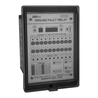
Monitors multiple circuits for ground faults, indicating leakage and fault current.
Performs circuit monitoring using an MCU and A/D converter for reliability.
Detects ground faults via ZCT input, amplified and processed by CPU.
CPU compares A/D converted input to settings, triggering fault indication.
Activates fault lamps and trips the circuit after the set operating time.
Identifies multiple circuit faults, displaying first detected, with recall via hold check.
Manual reset required after fault repair when in manual mode.
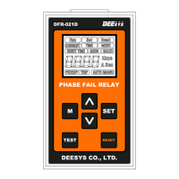
Button to cycle through monitored circuits and view fault levels.
Digital display showing the current circuit number being monitored.
Displays the detected earth leakage or fault current level numerically.
Stores and recalls the last recorded fault current level for a circuit.
Selects automatic or manual operation modes, with a warning lamp for auto mode.
Lamp illuminates for a leaking circuit when its self-test button is pressed.
Selects sensing current threshold (0.1A to 10A) based on line characteristics.
Sets the operating time interval for fault detection (0.05 to 10 seconds).
Simulates a ground fault to test circuit status and indicator lamps.
Table providing reference values for current and time settings.
Resets the entire relay function to its initial state.
Green LED indicating that the AC power supply is active.
Button to display and verify the set ground fault sensing current.
Button to display and verify the set operating time for a circuit.
Verify power connections, indicators, and settings before installation.
Ensure proper mounting, ZCT installation, and terminal connections.
Diagram illustrating the internal functional blocks of the GFR relay.
Diagram showing wiring for trip contacts and auxiliary outputs.
Diagrams and legends for terminal connections on various GFR models.
| Contact Form | SPDT |
|---|---|
| Contact Rating | 10A @ 250VAC, 10A @ 30VDC |
| Coil Voltage | 5VDC, 12VDC, 24VDC |
| Operate Time | 10 ms (max) |
| Release Time | 5ms max |