Do you have a question about the DEFA 800 Series and is the answer not in the manual?
Describes the connection for the central locking system.
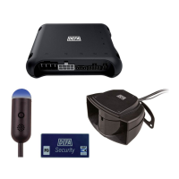
Details connections for auxiliary equipment like backup alarm, immobilizer module, and pager.
Specifies the connection for the main power supply via a 25A fuse.
Explains the starter kill input connection for specific models.
Details the connection for the ground lead to the vehicle body.
Outlines the starter kill output connection for specific models.
Describes the output for controlling the DEFA Car Heating System.
Explains the function of the Channel 2 output.
Details the output for the luggage compartment opener.
Covers the loop protecting auxiliary equipment like radio/cassette players.
Details the input for bonnet trigger when connected to ground.
Explains connection to the right turn signal lamp circuit.
Specifies the output connection for the siren.
Further specifies the output connection for the siren.
Details the connection to the ignition switch output.
Describes connection to the luggage compartment switch.
Explains an additional door switch input for negative switches.
Describes the output for controlling DEFA Power Module.
Explains connection to the left turn signal lamp circuit.
Refers to separate assembly instructions for auxiliary sensors.
Details the connection for the Glassbreak Sensor.
Details the connection for the Microwave Sensor.
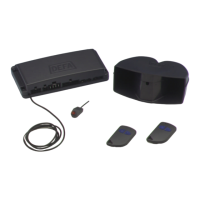
Explains installation of the LED indicator.
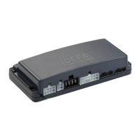
Instructions for positioning and mounting the central unit.
Guidance on locating and attaching the main fuse.
Recommendations for siren installation location and orientation.
Instructions for installing the Glassbreak Sensor.
Guidance on installing the LED indicator.
Preferred locations and considerations for Microwave Sensor installation.
Advice on optimal placement for the antenna feed lead.
Instructions for applying DEFA Auto Security decals to windows.
Important notes regarding installation and warranty.
Explains how to arm the alarm system using the remote control.
Describes how to arm the alarm without activating interior sensors.
Details the procedure to disarm the alarm system.
Provides steps for deactivating the alarm if the remote is lost or broken.
Explains the P-1 plug for central locking connection and configuration.
Explains how to check the cause of the last alarm trigger.
Details how to check the number of connected remote controls.
Describes how to select different alarm sound patterns.
Explains the passive arming feature and its modes.
Guides on adjusting the sensitivity of the microwave sensor.
Details programming modes for the remote control's slider switch.
Explains how to set the pulse duration for central locking.
Describes security features related to the central locking system.
Explains the starter kill and immobilizer functions.
Details how to automatically close windows or roof when arming.
Describes the panic function for remote triggering of the alarm.
Outlines the default factory settings for various alarm functions.
Details the procedure for entering the PIN code for the immobilizer.
Information regarding the EEC approval mark for the units.
| Category | Car Alarm |
|---|---|
| Frequency | 433.92 MHz |
| Immobilizer | Yes |
| Voltage | 12V |
| Remote Control | 2-button remote |
| Series | 800 Series |