Test scheme for modules ...;
in the PA DRL test adapter, DPL 10 slot
Test programme Pin at +/- Remark
XXXX 1
1
Þ
E
Test both polarities
XXXX 2
2
Þ
E
Test both polarities
XX 3
1
Þ
2
Test both polarities
XXXX 4
1
Þ
2
Pin 3 and 4 short-circuited internally
Upper slot X X X X Upper slot without EF 10 DRL earthing frame
Lower slot Lower slot
Test object According to contacting
Test object X X X X 1 to 10
DPL 10 F ARE...
DPL 10 F BaseT...
DPL 10 F ISDN 5...
DPL 10 G3...
DPL 10...
Type Part No.
Test programme
1 (1
Þ
E)
DPL 10 F ARE 24 907 110 28 38 28 38 - - 0 1
DPL 10 F ARE 110 907 111 134 166 134 166 - - 0 1
DPL 10 F ARE 12 907 112 15 21 15 21 - - 0 1
DPL 10 F 10BaseT 907 113 8 13 8 13 8 14 0 1
DPL 10 F ISDN 5 907 114 66 110 66 110 8 13 0 1
DPL 10 G3 110 907 214 182 279 182 279 - - 0 1
DPL 10 G3 110 FS 907 215 182 279 182 279 - - 0 1
DPL 10 G3 110 FSD 907 216 182 279 182 279 - - 0 1
Test programme
2 (2
Þ
E)
Test programme
3 (1
Þ
2)
Test programme
4 (1
Þ
2, 3-4)
Pin assignment
upper slot DPL 10, DRL
Pin assignment
lower slot DPL 10, DPL 1
Page
21
LLV
in [ V ]
ULV
in [ V ]
ULV
in [ V ]
LLV
in [ V ]
ULV
in [ V ]
LLV
in [ V ]
Tests have to be carried out with both polarities+/- and -/+!
Except for DPL 10 G3...
Prüfung
Test Pin
1: 1 E
2: 2 E
3: 1 2
4: 1 / 3
2 / 4
(bei: + / -)
(at: + / -)
Polarität
Polarity
+ / -
+ / -
Prüfung
Test
1
2
3
5
4
6
7
8
9
10
1
2
3
4
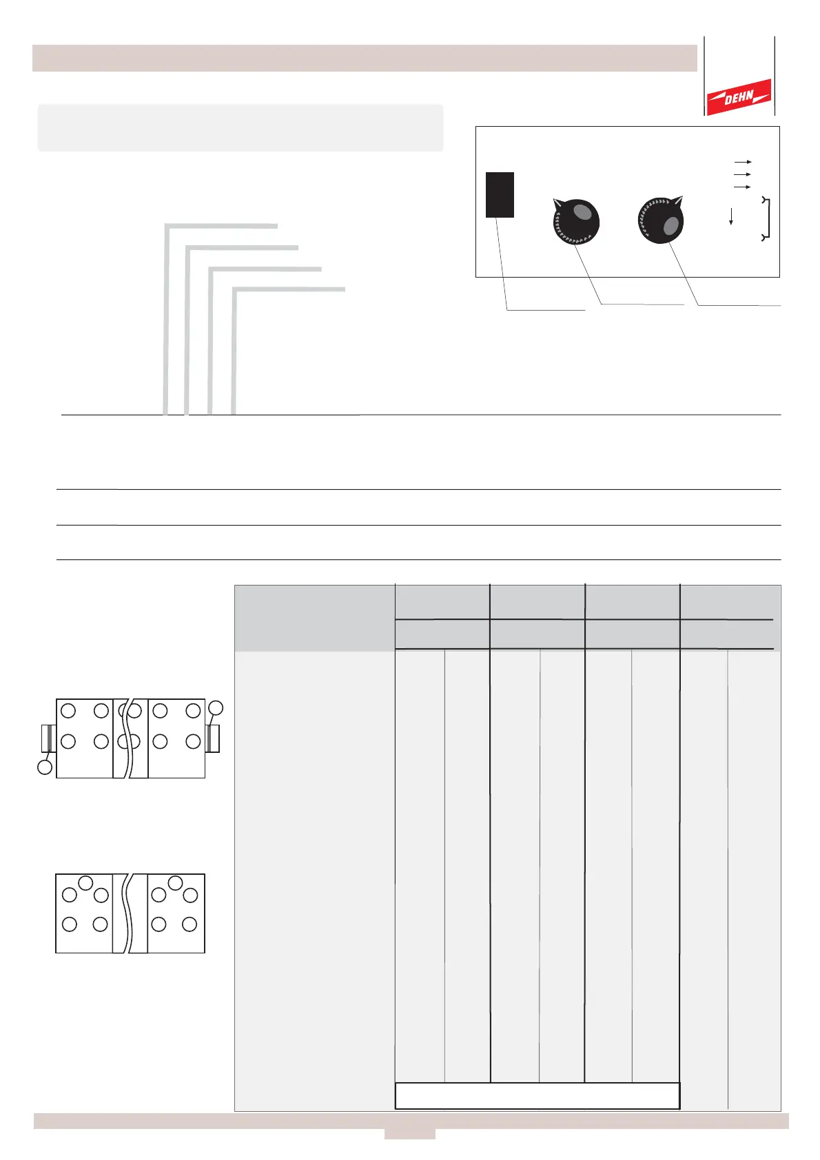
Prüfling
Test object
Programme
selector switch
Test circuit
selector switch
Polarity
selector switch
ULV
in [ V ]
LLV
in [ V ]
Test object
1 ... 10
Test object
1 ... 10
1 2
3 4
1 2
3 4
E
E
1
2
3
4
E
1
2
3
4
E
 Loading...