ENCODER IN
12 POLE
5VSE 5VDE
1
T2 (B)
T1 (A)
/
+5V
T2 (B)
GND
GND
GND
+5V
shield
GND
/
+5V
shield
GND
(GND)
+5V
T0 (REF)
T0 (REF)
T1 (A)
T1 T1
T1
/
T2
(+5V)
T0
/
T0
/
/
/
T2
T0
/
T2
2
3
4
5
6
7
8
9
10
11
12
ENCODER IN
9 POLE
12VSE
5VSE 5VDE
1
T0 (REF)
T0 (REF)
T2 (B)
T2 (B)
T1 (A)
+5V
+5V
In case of 12VSE
bridge pins 6,7,8 and 9
+5V
T1 (A)
+ 12V
+ 12V
GND
GND GND GND
T0
T0
T2
T2
T1
T1
T2
T1
T2
T1
/
/
/
/
/
T0
T0
2
3
4
5
6
7
8
9
T = Tandem
= CNC-ReaDY signal
= step Change
= R axis positive input
= Reference Search Direction switch
= Upper Dead Point
= End of Relaxation
= Lower Dead Point
= X-axis In Position
= Function output 1,2,3,4
CNC-RDY
C
R-in
RSD
UDP
ER
LDP
X-IP
F1,2,3,4
DM02
GND
0V
24V
24V
0V
H
H
L
L
HSB
H
L
HSB
120E
Shunt
DA6X
Pressure
25-Pole connectorFemale
Pen 5-7,10-11,18-19,22-24
of 25-Pole connector
are not connected
Valve Y1
Valve Y2
0-1500mA
Linear
Scale Y1
Valve Y1
System
Pressure
Valve Y2
Linear
Scale Y2
1
24V
0V
89 2 34131225142021151716
LVDT
Y1
+
1
2
S
2
1
S1 S2
2
1
-
D D
LVDT
Y2
+
1
2
S
2
1
S1 S2
2
1
-
D DD
MALE
12-Pole
Connector
Y2-Encoder
Input
MALE
12-Pole
Connector
Y1-Encoder
Input
In case hydraulic
Deflection unit is used
Amplifier
6-Pole Male connector
+
MALE
Servo
Amplifier
ME
9-Pole
Connector
X-Encoder
Input
10K
4-Pole Male connector
14
relais
24V
151617181920212223
OUT
A< A>
0V
relais
9
10
11 12 13
*1 *2
*3
*4
*5
*6
7
8
In case
motorized
deflection
is used
IN
OUTPUT
INPUT/OUTPUT
galvanic insulation
galvanic insulation
9+7+9 Pole Male connectors
INPUT
COM
COM
P I P II
A3
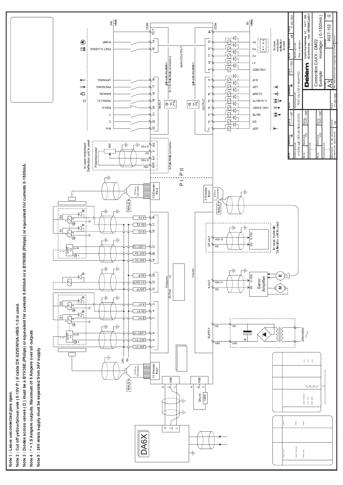
Connection DAXX - DM02
Example Hoerbiger ( 0-1500mA )
HM
VW
VW
MI MIMI
MI
Totally redrawn
31-08-1999
27-09-1995
16-01-1997
9027-102 G
-
-
-
-
22-07-1996
11-11-1997 13-11-1998
HYDRAULIC DEFLECTION ADDED TEXT 24V AND P SWAPPED
Note Note NoteRedrawn RedrawnRedrawn RedrawnDate Date Date
No unauthorized copying allowed
Format Number Issue
Note Redrawn
Redrawn
Date
Date
Date
Description
Description Description Description
Description
Note
DrawnMeasures in mm,unless
otherwise specified
Scale
Luchthavenweg 42, 5657 EB
Eindhoven, the NETHERLANDS
Note 1 : Leave unconnected pins open.
Note 2 : Cut off yellow/brown wire ( 0-10V P ) if cable DK-02VSW/VA-HBG-1.0 is used.
Note 3 : Diodes across valves ( D ) must be a BYV36E (Philips) or equivalent for currents 0-800mA or a BYM36E (Philips) or equivalent for currents 0-1500mA.
Note 5 : 24V relais supply must be separated from 24V supply
Note 4 : * = 1.5 Ampere outputs. Maximum of 9 Ampere over all outputs
 Loading...