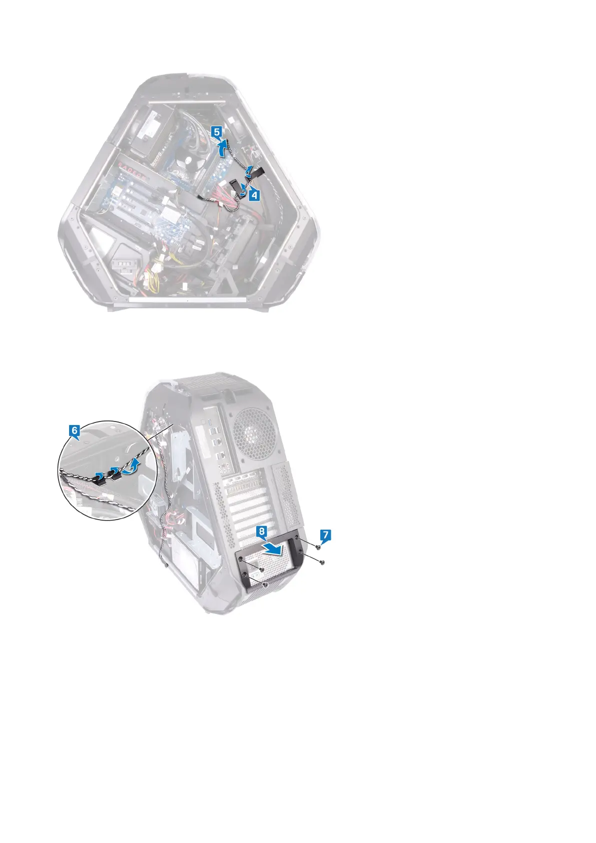
6. Remove the rear I/O accessibility lighting cable from the routing guides on the chassis.
7. Remove the four screws (#6-32x6) that secure the power-supply unit cover to the back of the chassis.
8. Lift the power-supply unit cover away from the chassis.
9. Remove the four screws (#6-32x6) that secure the rear bezel to the top and bottom of the chassis.
10.Remove the screw (M3x5) from inside, that secure the rear bezel to the chassis.
11. Release the tabs from inside the chassis on the left side, securing the rear bezel to the chassis.
12. Release the tabs from inside the chassis on the right side, securing the rear bezel to the chassis.
13. Remove the rear bezel from the chassis and remove the rear I/O accessibility lighting cable from the slot on the chassis.
92




 To Next Page