Do you have a question about the Dell EMC PowerEdge R650xs and is the answer not in the manual?
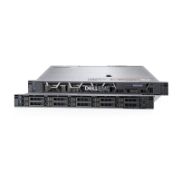
Details the components and ports visible on the front of the server system.
Describes the indicators and buttons located on the left control panel.
Explains the components and ports found on the right control panel.
Illustrates and lists the various ports and connectors on the rear of the server.
Provides a visual overview of the internal components and their locations within the chassis.
Guides users on how to find the unique system identification codes for the server.
Details the location and content of the system information label on the server.
Provides information on compatible rail kits and rack specifications for system installation.
Outlines the essential steps for initial system installation and physical setup.
Explains the process and options for configuring the Integrated Dell Remote Access Controller (iDRAC).
Lists available resources and documentation for installing the operating system.
Defines the essential components required for the system to power on and POST.
Describes how the system verifies its configuration against qualified settings during startup.
Details specific error messages encountered during system configuration validation.
Provides critical safety precautions to be followed before performing any component installation or removal.
Outlines prerequisites and steps before accessing internal system components.
Details steps required after internal component work before powering on the system.
Lists the necessary tools for performing component removal and installation procedures.
Describes the procedure for removing and installing the optional front bezel.
Explains how to remove and install the main system cover of the server.
Details the steps for removing and installing the drive backplane cover.
Instructions for removing and installing the air shroud for proper system cooling.
Procedures for removing and installing system cooling fans.
Steps for removing and installing the intrusion switch module.
Covers the removal and installation of drive blanks and drive carriers.
Procedure for removing and installing an optional optical drive.
Information on supported drive backplane options and their removal/installation.
Illustrates cable connections for various drive backplane configurations.
Guidelines and procedures for installing and removing system memory modules (DIMMs).
Detailed steps for removing and installing the processor and its heat sink module.
Information on expansion card slot configurations and installation guidelines.
Procedures for removing and installing the 2.5-inch rear drive cage.
Instructions for removing and installing an optional serial COM port module.
Steps for removing and installing MicroSD cards.
Procedures for removing and installing the M.2 BOSS riser and cards.
Steps for removing and installing the optional IDSDM module.
Procedures for removing and installing an optional OCP card.
Instructions for removing and installing the front-mounted PERC module.
Details the procedure for replacing the system battery.
Steps for removing and installing an optional internal USB card.
Procedures for removing and installing the VGA module.
Information on PSU functionality, hot-spare features, and installation/removal.
Instructions for removing and installing the power interposer board.
Procedures for removing and installing the system board.
Information on TPM installation, upgrading, and initialization.
Procedures for removing and installing the left and right control panels.
Identifies and describes the various connectors found on the system board.
Details the settings for system board jumpers and their functions.
Provides instructions on how to reset system passwords using jumpers.
Explains the status LEDs on the system and their meanings.
Describes the system health and ID indicator codes on the control panel.
Details the indicator codes for the optional iDRAC Quick Sync 2 feature.
Explains the indicator codes for the iDRAC Direct port.
Information about the LCD panel's features, status, and operation.
Describes the indicator codes for the Network Interface Cards (NICs).
Explains the status indicator codes for the Power Supply Units (PSUs).
Details the indicator codes for the drives, showing their status.
Guidance on running system diagnostics to test hardware and troubleshoot issues.
Information on recycling and disposal services for system components.
Provides steps for contacting Dell support for technical assistance and service.
Explains how to use the Quick Resource Locator (QRL) for system information.
Information on Dell EMC SupportAssist for automated technical support.
| Form Factor | 1U Rack Server |
|---|---|
| Processor | Up to two 3rd Generation Intel Xeon Scalable processors, with up to 32 cores per processor |
| Memory | Up to 1TB DDR4 ECC RDIMM, speeds up to 3200MT/s; 16 DIMM slots |
| Storage | Up to 10 x 2.5" SAS/SATA/NVMe drives, or up to 4 x 3.5" SAS/SATA drives |
| RAID Controller | PERC H745, H755, H755N, HBA355i |
| Power Supply | 1100W |
| PCIe Slots | Up to 3 x PCIe Gen4 slots |
| Operating System Support | Canonical Ubuntu Server LTS, Citrix Hypervisor, Microsoft Windows Server with Hyper-V, Red Hat Enterprise Linux, SUSE Linux Enterprise Server, VMware ESXi |
| Management | iDRAC9 with Lifecycle Controller |
| Network | OCP 3.0 options |