4. Remove the battery.
5. Remove the 4G WWAN card or 5G WWAN card, as applicable.
6. Remove the WLAN card.
7. Remove the memory modules.
8. Remove the M.2 2230 or M.2 2280 solid-state drive from Slot 1.
9. Remove the M.2 2230 solid-state drive from Slot 2.
10. Remove the coin-cell battery.
11. Remove the heat sink.
12. Remove the assembly inner frame.
About this task
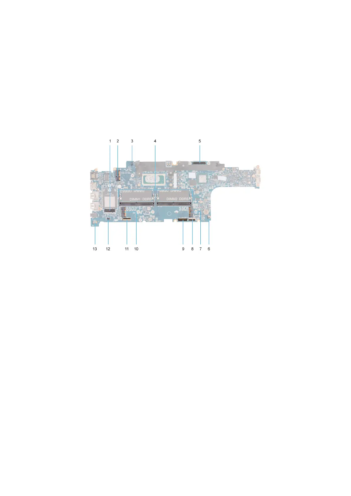
The following images indicate the system board connectors.
1. WWAN card connector 2. WLAN card connector
3. eDP cable connector 4. Memory modules
5. Display cable connector 6. System fan connector
7. Solid-state drive Slot 1 8. Touchpad cable connector
9. Battery cable connector 10. Solid-state drive Slot 2
11. USH-cable connector 12. Coin-cell battery cable connector
13. Speaker cable connector
The following images indicate the location of the system board and provide a visual representation of the removal procedure.
84
Removing and installing Field Replaceable Units (FRUs)