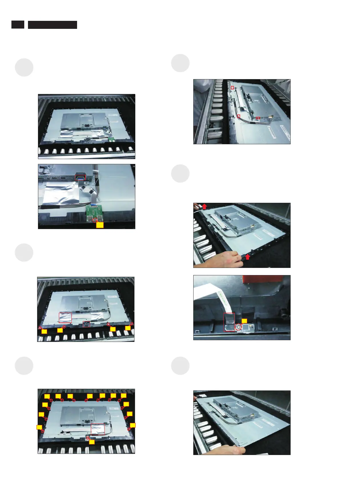
Disconnect the LED cable from the connector of the
interface board, then release the LED cable by
tearing off the tapes.
S13
S10
S12
S14
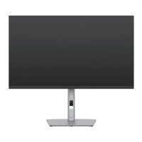
Use a Philips-head screwdriver to release 1 screws
for unlocking the USB board, then disconnect the
USB FFC cable away from the connector of the
interface board and remove the Usb board unit.
(No.1screw size=M3x6, Torque=4±0.5kgfxcm)
S11
2
DELL P3221D
S9
1
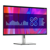
Tear off 1pcs conductive tape and 1pcs aluminum foil
as the picture below shown. Use a Philips-head
screwdriver to remove 4pcs screws for unlocking the
middle bezel with front bezel.
(No.1~4 screw size=M2x3.5, Torque=2.5±0.5kgfxcm)
1
4
2
3
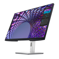
Use a Philips-head screwdriver to remove 14pcs
screws for unlocking the middle bezel with the panel
module, then tear off the aluminum foil for unlocking
the cables and bracket.
(No.1~14 screw size=M3x5, Torque=5±0.5kgfxcm)
3
14
2
1
4
5
6
7
8
9
10
11
12
13
Take away the middle bezel, and put it on a fixture.
U
tear off the tape for releasing the
LED cable.
se a Philips-head screwdriver to remove 1pcs
screw for unlocking the LED board with the middle
bezel, and then
(No.1~3 screw size=M2x2.4, Torque=0.8±0.2kgfxcm
2
Lift up the panel module with the bracket chassis for
releasing the front bezel away from the panel
module. Disconnect the panel lamp cables away
from the connectors of the interface board and the
panel module.