12 PowerEdge R520 Technical Guide
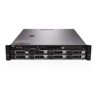
Chassis features
Table 4 lists the features on the R520 chassis. For additional information, see the
Dell PowerEdge
R520 Systems Owner’s Manual
on Dell.com/Support/Manuals.
Table 4. Chassis features
ACPI-compliant power button with an integrated green power LED
Covers the system’s front-loading hard drives and locks for security
Used to troubleshoot software and device driver errors; use only if directed
to do so by qualified support personnel or by the operating system's
documentation
System identification button
Buttons on the back and front of a system to help identify the unit in a data
center environment
Up to eight 3.5-inch drives
Connects USB devices to the server
Slide-out label panel for recording system information
Connects a monitor to the server
Displays system ID, status information and system error messages; two
navigation buttons to scroll through the menu on the LCD and one select
button
Optional slim DVD or DVD+RW drive
Supplies power to the server
Indicates whether server has power
Indicates network activity and status
Connects PCIe expansion cards to the server
Connects integrated 10/100/1000 NICs to the server
Connects a serial device to the server
Dedicated management port for optional iDRAC card
Front control panel
The R520 control panel is located on the front of the chassis as shown in Figure 5. For more
information about the LCD control panel, see the
Dell PowerEdge R520 Systems Owner’s Manual
on
Dell.com/Support/Manuals.

 Loading...