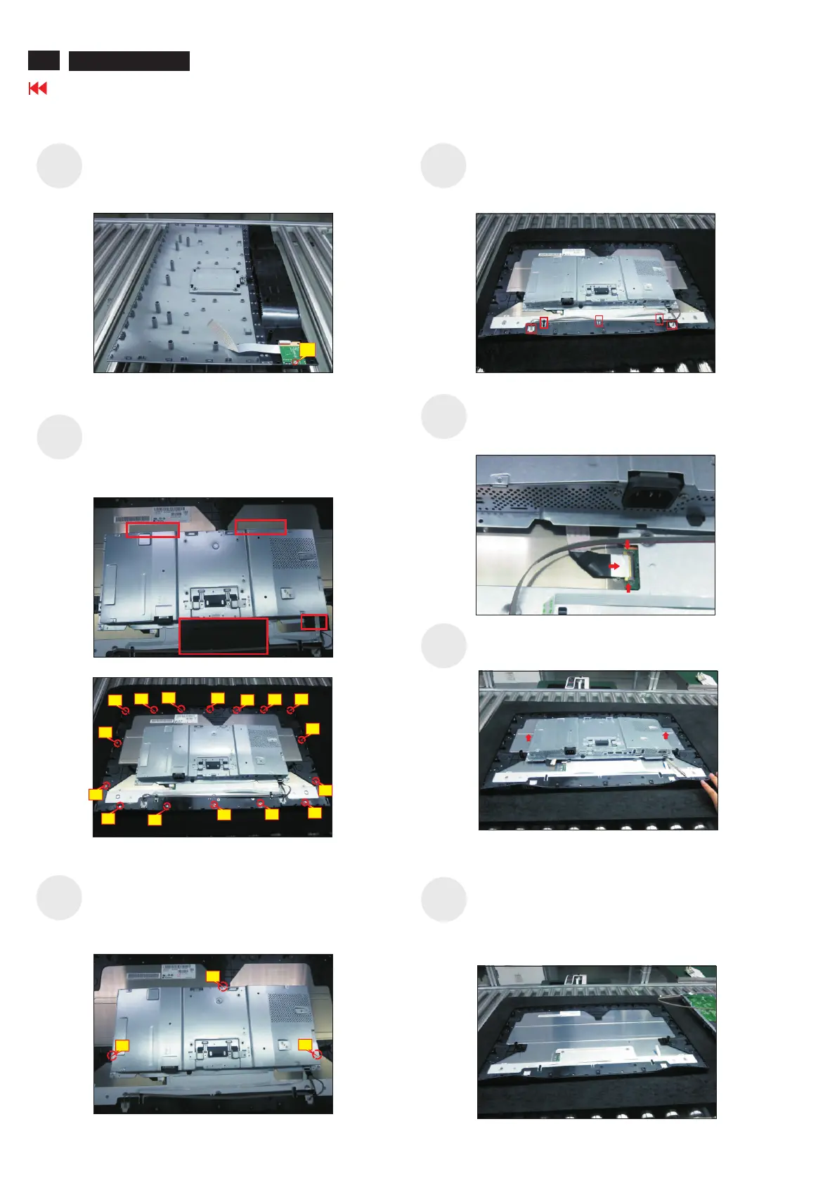
Disconnect the panel power cable from the two
connector of the panel module, then release the
panel power cables from the hooks of the middle
bezel.
Tear off 4pcs aluminum foil for releasing the bracket.
Use a Philips-head screwdriver to release 12 screws
for unlocking the middle bezel away from the
assembled unit.
(No.1~12 screw size=M3x4, Torque=3~4kgfxcm)
S9
U
.
se a Philips-head screwdriver to remove four
screws for unlocking the bracket chassis module
with the panel module
(No.1~4 Screw size= M3x0.5x4, Torque=3~4kgfxcm)
S13
S10
Move up the bracket, then push the earing-lock and
disconnect the EDP cable away from the connector of
the panel module.
S11
S12
Remove the bracket chas
sis mo
dule and th
en put th
e
bra
cket on a protector c
ush
ion.
Tear off the adhesive tape for releasing the function
key cable, and then r
a
Philips-head screwdriver to remove 3pcs screws for
unlocking the function key board.
emove the middle bezel with the
function key board. Tear off the mylar tape, then use
(No.1~3 screw size=M2x2.4, Torque=0.8~1kgfxcm)
S14
2
Go to contents page
U2720Q/Q2720QM
Use a Philips-head screwdriver to remove 1pcs
screw for unlocking the USB board unit, then release
the USB board unit and put it aside.
(No.1 screw size=M3x6, Torque=4±0.5kgfxcm)
1
S8
1
2
3
3
10
2
9
7
4
11
13
1
8
5
6
14
12
15
16