D:05:02
Fuel,
Emission and Exhaust System
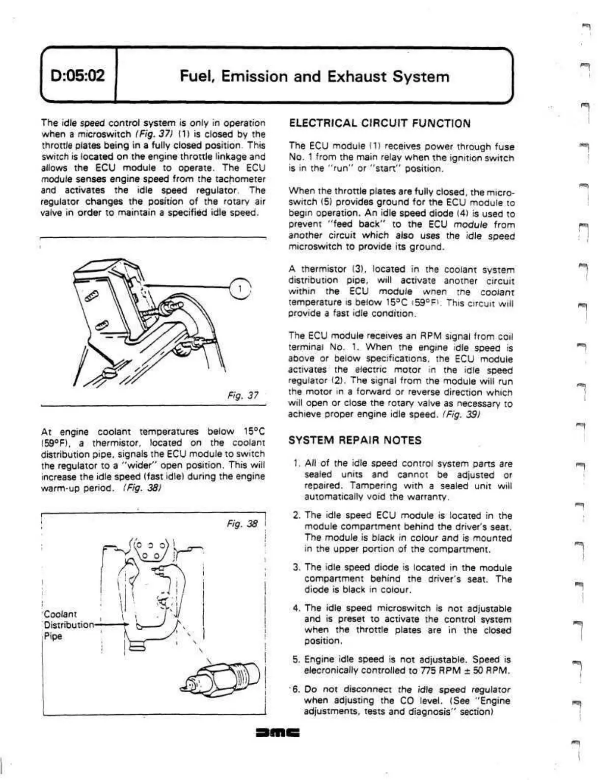
The idle speed control system is only in operation
when a microswitch (Fig. 37)
(1)
is closed by the
throttle plates being in a fully closed position. This
switch is located on the engine throttle linkage and
allows the ECU module to operate. The ECU
module senses engine speed from the tachometer
and activates the idle speed regulator. The
regulator changes the position of the rotary air
valve in order to maintain a specified idle speed.
Fig. 37
At engine coolant temperatures below
15°C
(59°F), a thermistor, located on the coolant
distribution pipe, signals the ECU module to switch
the regulator to a "wider" open position. This will
increase the idle speed (fast idle) during the engine
warm-up period.
(Fig.
38)
Fig. 38
Coolant
Distribution
Pipe
ELECTRICAL CIRCUIT FUNCTION
The ECU module (1) receives power through fuse
No.
1
from the main relay when the ignition switch
is in the "run" or "start" position.
When the throttle plates are fully closed, the micro-
switch (5) provides ground for the ECU module to
begin operation. An idle speed diode (4) is used to
prevent "feed back" to the ECU module from
another circuit which also uses the idle speed
microswitch to provide its ground.
A thermistor (3), located in the coolant system
distribution pipe,
will
activate another circuit
within the ECU module when the coolant
temperature is below
15°C
i59°R.
This
circuit will
provide a fast idle condition.
The ECU module receives an
RPM
signal from coil
terminal No.
1.
When the engine idle speed is
above or below specifications, the ECU module
activates the electric motor in the idle speed
regulator (2). The signal from the module will run
the motor in a forward or reverse direction which
will open or close the rotary valve as necessary to
achieve proper engine idle speed. (Fig. 39)
SYSTEM REPAIR NOTES
1.
All of the idle speed control system parts are
sealed units and cannot be adjusted or
repaired.
Tampering with a sealed unit will
automatically void the warranty.
2.
The idle speed ECU module is located in the
module compartment behind the driver's seat.
The module is black in colour and is mounted
in the upper portion of the compartment.
3. The idle speed diode is located in the module
compartment behind the driver's seat. The
diode is black in colour.
4.
The idle speed microswitch is not adjustable
and is preset to activate the control system
when the throttle plates are in the closed
position.
5. Engine idle speed is not adjustable. Speed is
elecronically controlled to 775 RPM ± 50 RPM.
6.
Do not disconnect the idle speed regulator
when adjusting the CO level. (See "Engine
adjustments, tests and diagnosis" section)
P
i
fS:
-|
 Loading...
