••
3. Disconnect tube from transmission arm and
adjust tube until bellcrank is aligned at
approximately 90 degrees to centreline of
chassis when tube is connected and
transmission is in neutral.
4.
Working through access hole in chassis centre
backbone, disconnect front gear change tube
from bellcrank.
5. Loosen locknut on gear change tube and turn
end of tube to adjust.
Lengthening rod moves shift pattern closer to
driver.
6. Tighten lock nut and install tube on bellcrank.
SHIFT LEVER ASSEMBLY
REMOVAL AND INSTALLATION
1.
Remove gear shift knob.
2.
Remove two screws securing gear shift trim
plate to console. Disconnect wires and remove
plate.
3. Remove retaining clip and pin securing shift
cable to shift lever clevis.
4.
Remove bolts securing shift lever assembly to
chassis.
5. Disconnect front gear change tube by lifting
assembly out of chassis to gain access to
securing pivot bolt.
6. Remove shift lever assembly.
7. Reverse above procedure for installation.
SHIFT CABLE
REMOVAL AND INSTALLATION
1.
Remove the gear shift knob.
2.
Remove two screws
secuiing
gear shift trim
plate to console. Disconnect wires and remove
the plate.
3. Remove retaining clip and pin securing the
shift cable to shift lever clevis.
4.
Remove nut securing cable to chassis.
5. Raise vehicle on hoist and disconnect cable at
transmission arm.
6. Remove rear cable adjusting nut and pull cable
assembly out of mounting bracket.
7. Remove shift cable by pulling out of chassis.
NOTE:
Cable may be secured inside chassis
backbone with tie strap.
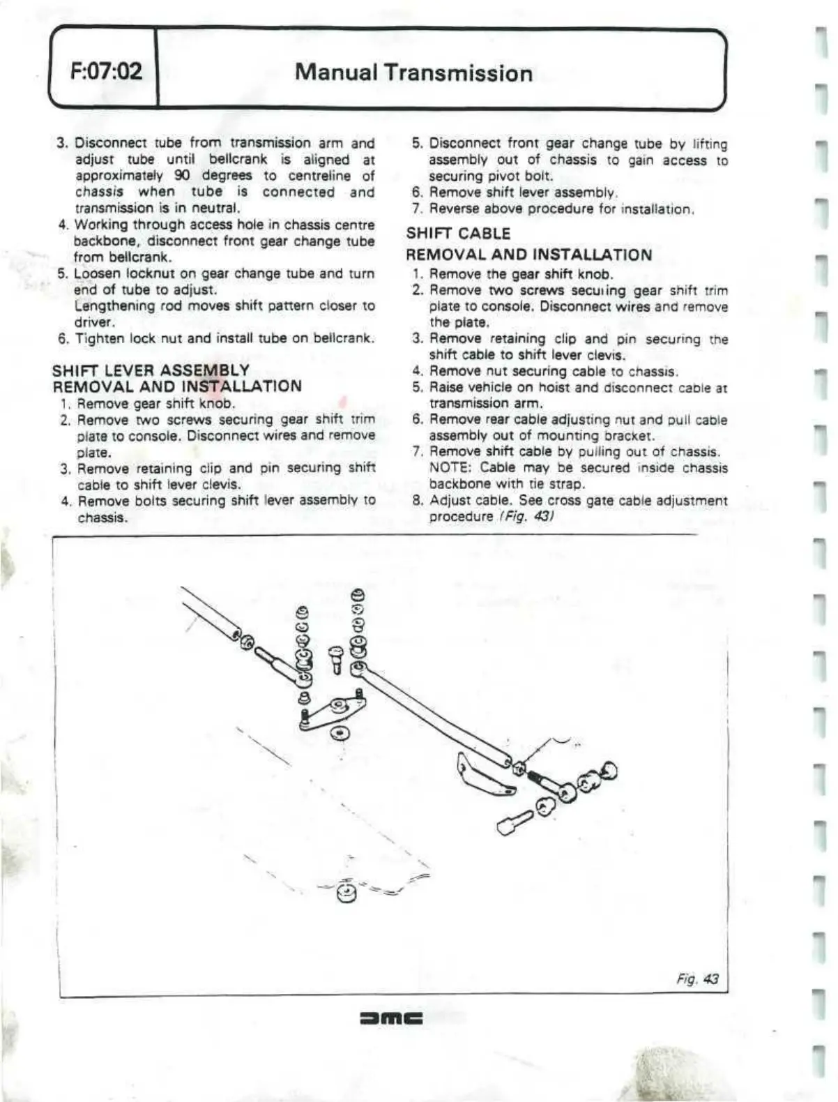
8. Adjust cable. See cross gate cable adjustment
procedure (Fig. 43)
.
 Loading...
