r
G:01:02
Automatic Transmission
achieved by locking certain members of the
planetary gear set. Locking of gear members is
performed by applying fluid pressure to one or
more of the brakes and clutches (B1, B2, C1 and
C2).
The hydraulic system is pressurized by an involute
gear fluid pump which is shaft driven directly by
the engine. A vacuum modulator is used to sense
engine torque input to the transmission and adjust
the fluid pressure accordingly. Line fluid pressure
is increased during high torque requirements to
ensure positive application of clutches and brakes.
Fluid
pressure
distribtion is performed by the valve
body. A manually operated selector valve directs
fluid pressure to the proper passages which lead to
the appropriate brakes or clutches. The shift valves
in the valve body are controlled by two electric
solenoid bail valves. Opening or closing of the
solenoids will activate the appropriate shift valve
which will in turn create a gear change.
The electrical solenoids Fig. 2 receive their
information from the governor computer
assembly. The gear driven governor is a low output
alternator that produces current which varies with
output shaft speed and throttle position. Current
from the governor supplies information to the
computer. Depending on governor current and
gear selector position, the computer will activate or
de-activate one or both of the solenoid valves, thus
providing a gear ratio change at the proper speed.
The governor computer also ensures that 1st gear
cannot be selected above 22 MPH (35 km/h) on
light throttle.
Fig. 2 VALVE BODY AND ELECTRIC SHIFT
SOLENOIDS
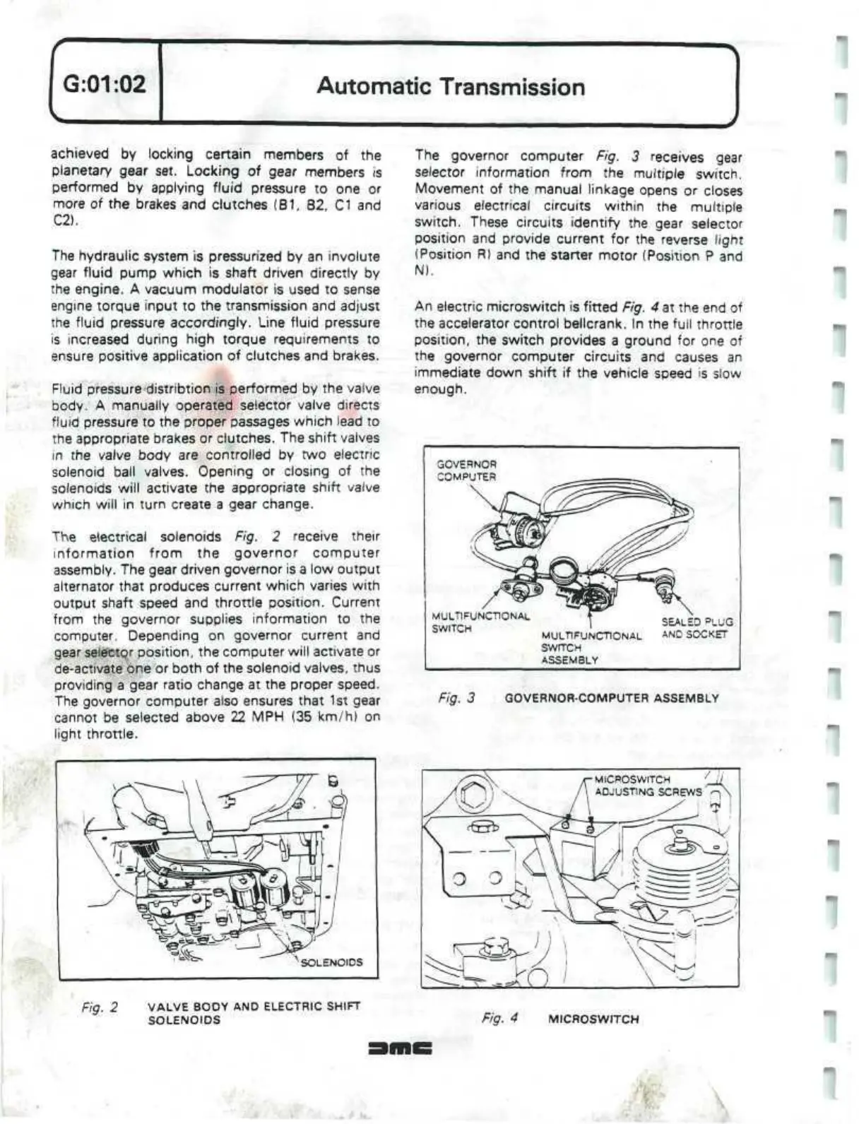
The governor computer Fig. 3 receives gear
selector information from the multiple switch.
Movement of the manual linkage opens or closes
various electrical circuits within the multiple
switch.
These circuits identify the gear selector
position and provide current for the reverse light
(Position R) and the starter motor (Position P and
N).
An electric
microswitch
is fitted Fig. 4 at the end of
the accelerator control bellcrank. In the full throttle
position,
the switch provides a ground for one of
the governor computer circuits and causes an
immediate down shift if the vehicle speed is slow
enough.
MULTIFUNCTIONAL
SWITCH
SEALED
PLUG
MULTIFUNCTIONAL
AN
0
SOCKET
swrrcH
ASSEMBLY
Fig. 3 GOVERNOR-COMPUTER ASSEMBLY
Fig. 4 MICROSWITCH
.
 Loading...
