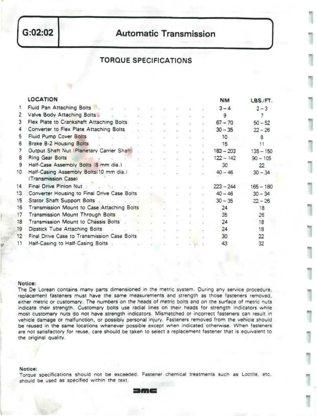
G:02:02
Automatic Transmission
TORQUE SPECIFICATIONS
LOCATION
1 Fluid Pan Attaching Bolts
2 Valve Body Attaching Bolts .
3 Flex Plate to Crankshaft Attaching Bolts
4 Converter to Flex Plate Attaching Bolts
5 Fluid Pump Cover Bolts
6 Brake B-2 Housing Bolts
7 Output Shaft Nut (Planetary Carrier Shaft)
8 Ring Gear Bolts
9 Half-Case Assembly Bolts (8 mm dia.) .
10 Half-Casing Assembly
BoltsdO
mm dia.)
(Transmission Case)
14 Final Drive Pinion Nut ....
13 Converter Housing to Final Drive Case Bolts
15 Stator Shaft Support Bolts .
16 Transmission Mount to Case Attaching Bolts
17 Transmission Mount Through Bolts
18 Transmission Mount to Chassis Bolts
19 Dipstick Tube Attaching Bolts
12 Final Drive Case to Transmission Case Bolts
11 Half-Casing to Half-Casing Bolts .
NM
3-4
9
67-70
30-35
10
15
183-203
122-142
30
40-46
223-244
40-46
30-35
24
35
24
24
30
43
LBS.IFT.
2-3
7
50-52
22-26
8
11
135-150
90-105
22
30-34
165-180
30-34
22-26
18
26
18
18
22
32
Notice:
The De Lorean contains many parts dimensioned in the metric system. During any service procedure,
replacement fasteners must have the same measurements and strength as those fasteners removed,
either metric or customary. The numbers on the heads of metric bolts and on the surface of metric nuts
indicate their strength. Customary bolts use radial lines on their heads for strength indicators while
most customary nuts do not have strength indicators. Mismatched or incorrect fasteners can result in
vehicle damage or malfunction, or possibly personal injury. Fasteners removed from the vehicle should
be reused in the same locations whenever possible except when indicated otherwise. When fasteners
are not satisfactory for reuse, care should be taken to select a replacement fastener that is equivalent to
the original quality.
Notice:
Torque specifications should not be exceeded. Fastener chemical treatments such as Loctite, etc.
should be used as specified within the text.
 Loading...
