Automatic Transmission G:08:05
i
'
M
p77iT|
F0*t\
Fig. 50
BRAKE
B-1
DISC PACK
ROLLER CLUTCH
The roller clutch is part of the clutch C1 assembly
and must be removed from the assembly for repair.
Disassembly
1.
Remove the turbine shaft from the clutch
CI
by using a brass drift and hammer to free the
shaft from the retaining clip.
2.
Remove the roller clutch assembly from the
clutch C1 housing as follows:
Install the special tool J
29351 (part
of the A/T
Tool Kit) on the clutch housing aligning the
depressing screws with the holes in the clutch
housing.
Tighten the screws evenly until the
lock ring is released and pull the assembly free
from the housing. Fig. 51
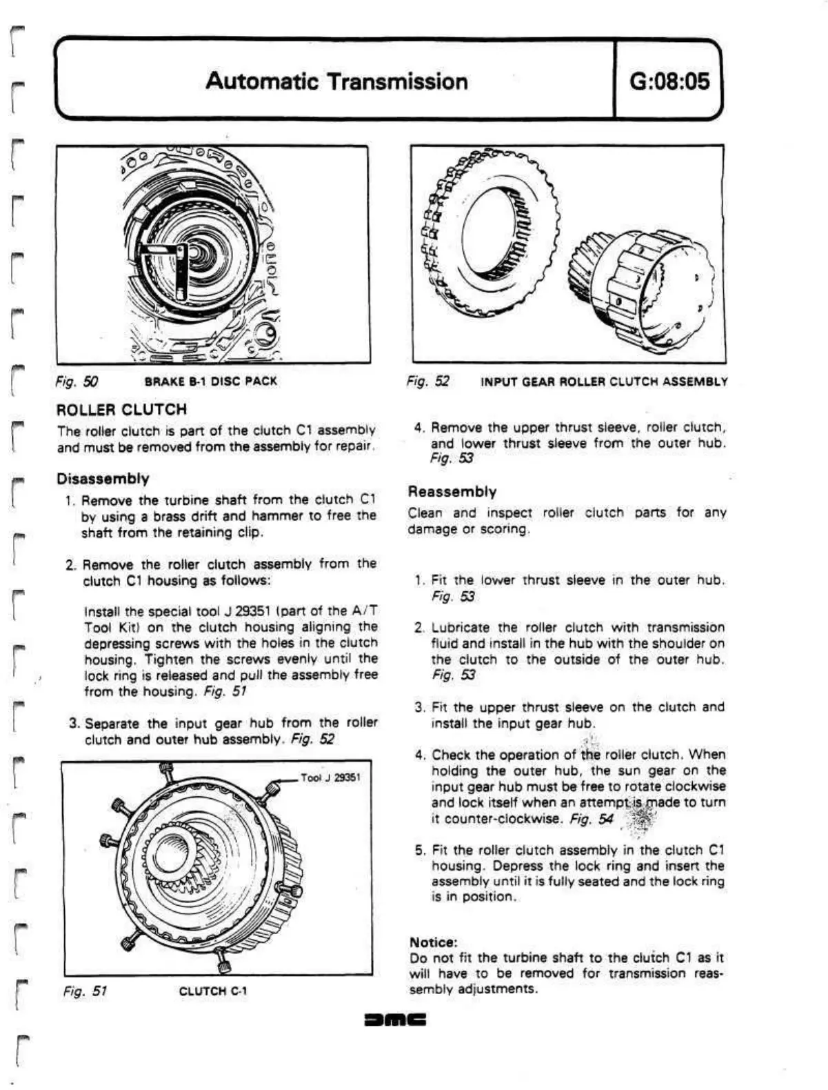
3. Separate the input gear hub from the roller
clutch and outer hub assembly. Fig. 52
Fig.
51
CLUTCH
C-1
Fig. 52 INPUT GEAR ROLLER CLUTCH ASSEMBLY
4.
Remove the upper thrust sleeve, roller clutch,
and lower thrust sleeve from the outer hub.
Fig. 53
Reassembly
Clean and inspect roller clutch parts for any
damage or scoring.
1.
Fit the lower thrust sleeve in the outer hub.
Fig. 53
2.
Lubricate the roller clutch with transmission
fluid and install in the hub with the shoulder on
the clutch to the outside of the outer hub.
Fig. 53
3. Fit the upper thrust sleeve on the clutch and
install the input gear hub.
4.
Check the operation of the roller clutch. When
holding the outer hub, the sun gear on the
input gear hub must be free to rotate clockwise
and lock itself when an
attempt|s.;jmade
to turn
it counter-clockwise. Fig. 54
f|f|||'
5. Fit the roller clutch assembly in the clutch C1
housing.
Depress the lock ring and insert the
assembly until it is fully seated and the lock ring
is in position.
Notice:
Do not fit the turbine shaft to the clutch C1 as it
will have to be removed for transmission reas-
sembly adjustments.
|f^'^T\
 Loading...
