%*
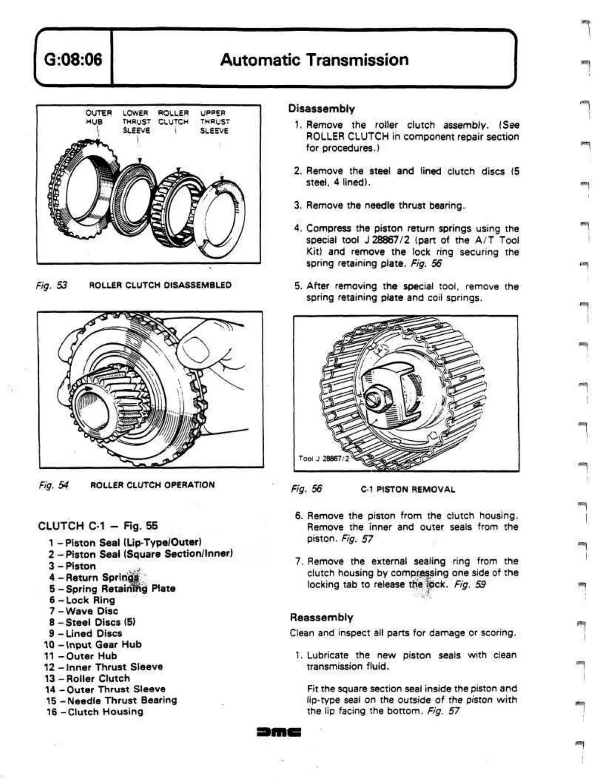
OUTER
HUB
I
//"""In
^^0mk
LOWER
THRUST
SLEEVE
i
ROLLER
CLUTCH
i
aijf
p.
UPPER
THRUST
SLEEVE
w'/%\
\ J
J
Fig. 53 ROLLER CLUTCH DISASSEMBLED
Disassembly
1.
Remove the roller clutch assembly. (See
ROLLER CLUTCH in component repair section
for procedures.)
2.
Remove the steel and lined clutch discs (5
steel,
4 lined).
3. Remove the needle thrust bearing.
4.
Compress the piston return springs using the
special tool J 28867/2 (part of the A/T Tool
Kit) and remove the lock ring securing the
spring retaining plate. Fig. 56
5. After removing the special
tool,
remove the
spring retaining plate and coil springs.
Fig. 54 ROLLER CLUTCH OPERATION
Fig. 56
C-1 PISTON REMOVAL
CLUTCH C-1 - Fig. 55
1 - Piston Seal (Lip-Type/Outer)
2 - Piston Seal (Square Section/Inner)
3-Piston
,
4 - Return
Springs
5 -Spring
Retainmg
Plate
6 - Lock Ring
7 - Wave Disc
8-Steel
Discs (5)
9 - Lined Discs
10 -
Input
Gear Hub
11 -Outer Hub
12 -Inner Thrust Sleeve
13 -Roller Clutch
14 -Outer Thrust Sleeve
15 -Needle Thrust Bearing
16 -Clutch Housing
6. Remove the piston from the clutch housing.
Remove the inner and outer seals from the
piston.
Fig. 57
7. Remove the external sealing ring from the
clutch housing by compressing one side of the
locking tab to release
tlrie
l^ck.
Fig. 59
Reassembly
Clean and inspect all parts for damage or scoring.
1.
Lubricate the new piston seals with clean
transmission
fluid.
Fit the square section seal inside the piston and
lip-type seal on the outside of the piston with
the lip facing the bottom. Fig. 57
 Loading...
