r
^
r
\
Automatic Transmission
G
.09:05
ffW\
i'V>""'l
^7)
Notice:
If the differential adjusting nuts were not moved
and the pinion gear assembly was not dis-
assembled,
the differential adjustments will not
have to be performed during final drive re-
assembly.
Example:
120.00 mm
-46.48 mm
73.52 mm
Set Value
Distance Measurement X
Dimension A
f. The final dimension should be as near as
possible to 73.6 mm (2.898 in.). If it is not
close to 73.6 mm, the thickness of the shim
pack under the bearing race C Fig.
73 in
the
planetary housing will have to be increased
or decreased.
g.
Remove and disassemble the planetary
gear carrier assembly.
h. Remove the bearing race from the
planetary gear carrier housing and adjust
the'shim
pack to obtain the proper final
dimension measurement.
i. Install the bearing race using a brass drift.
Fit the roller bearing in
.the
race and install
the new lip-seal.
j.
Reassemble the planetary gear carrier and
torque tighten the lock nut. Lock (peen)
the nut to the shaft (see torque specific-
ations).
Reassembly
Notice:
The ring and pinion gears are not serviced
separately.
If
one part is damaged, they must be
replaced as a set.
1.
Press the inner pinion bearing onto the pinion
gear shaft.
2.
Install the governor drive gear.
3. Install the secondary gear with the flat face of
the gear towards the head of the pinion gear.
4.
Install the spacer with the larger diameter end
facing the secondary gear.
5. Install the outer pinion bearing and nut.
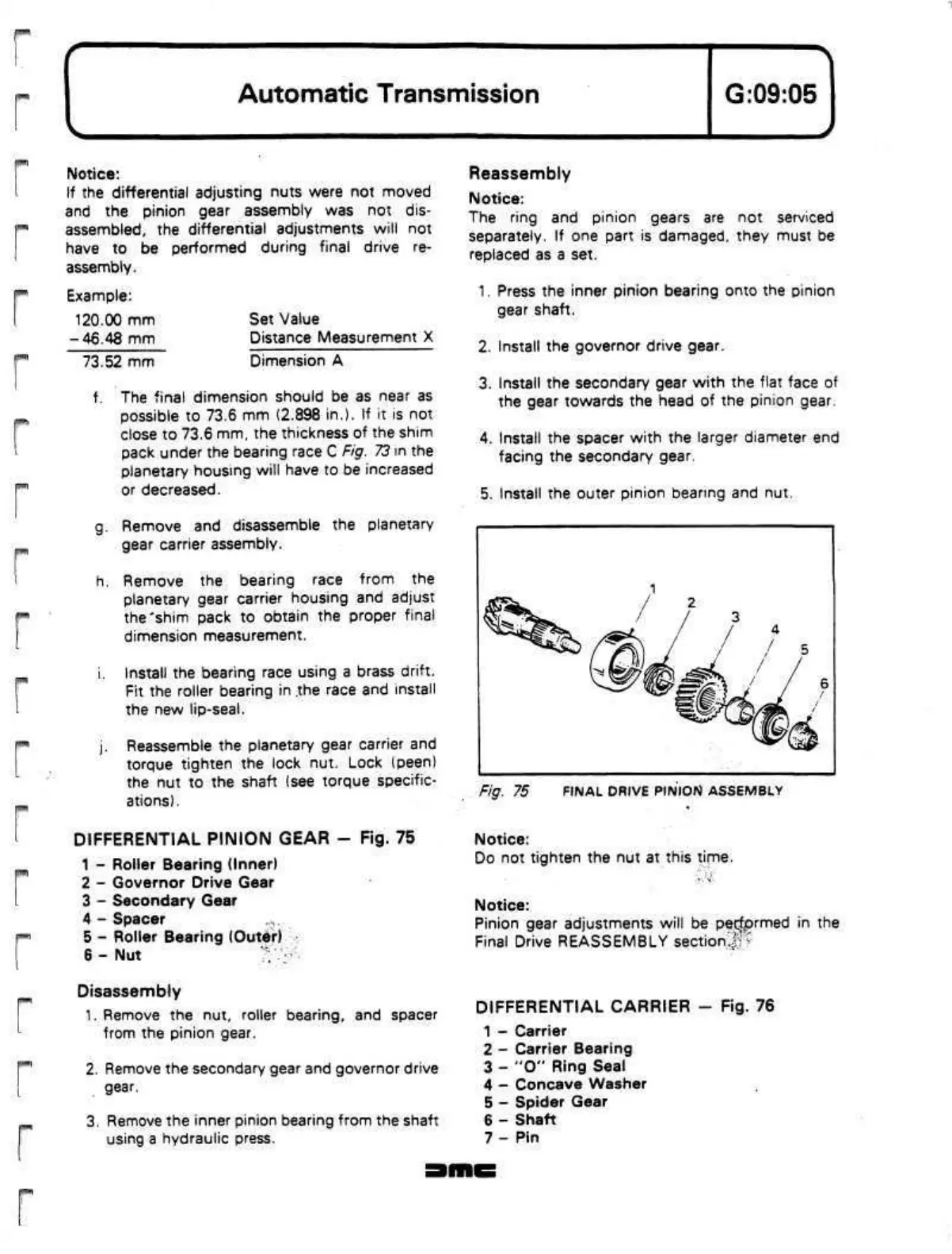
Fig. 75 FINAL DRIVE PINION ASSEMBLY
DIFFERENTIAL PINION GEAR
-
Fig. 75
1 - Roller Bearing (Inner)
2 - Governor Drive Gear
3 - Secondary Gear
4 - Spacer
5 - Roller Bearing
(Outer)
6 - Nut
?;
-
Notice:
Do not tighten the nut at this time.
Notice:
Pinion gear adjustments will be
performed
in the
Final Drive REASSEMBLY
section•&$•
r^mt
Disassembly
1.
Remove the nut, roller bearing, and spacer
from the pinion gear.
2.
Remove the secondary gear and governor drive
gear.
3. Remove the inner pinion bearing from the shaft
using a hydraulic press.
DIFFERENTIAL CARRIER - Fig. 76
1 - Carrier
2 - Carrier Bearing
3 -
"O"
Ring Seal
4 - Concave Washer
5 - Spider Gear
6 - Shaft
7- Pin
 Loading...
