r
G:09:06
Automatic Transmission
^v
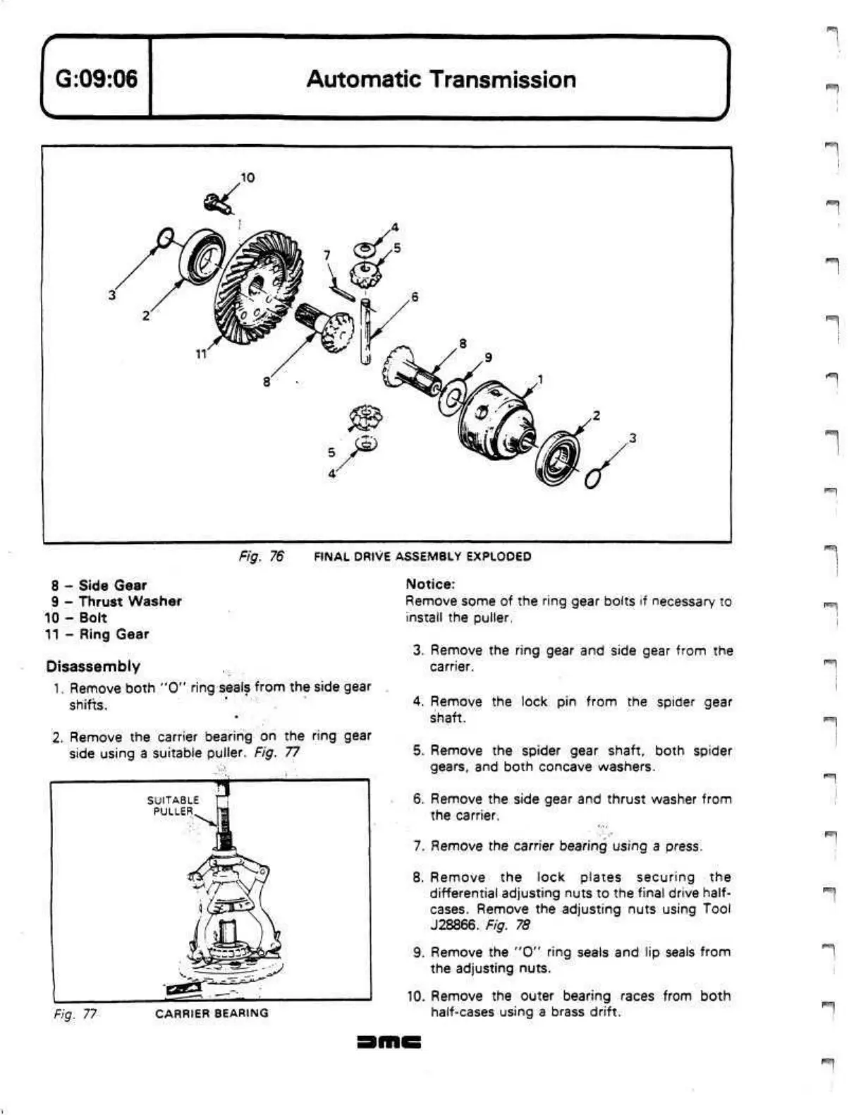
Fig. 76 FINAL DRIVE ASSEMBLY EXPLODED
8 - Side Gear
9 - Thrust Washer
10 - Bolt
11 - Ring Gear
Disassembly
1.
Remove both "0" ring seals from the side gear
shifts.
2.
Remove the carrier bearing on the ring gear
side using a suitable puller. Fig. 77
Fig. 77
CARRIER BEARING
Notice:
Remove some of the ring gear bolts if necessary to
install the puller.
3. Remove the ring gear and side gear from the
carrier.
4.
Remove the lock pin from the spider gear
shaft.
5. Remove the spider gear shaft, both spider
gears,
and both concave washers.
6. Remove the side gear and thrust washer from
the carrier.
7. Remove the carrier bearing using a press.
8. Remove the lock plates securing the
differential adjusting nuts to the final drive half-
cases. Remove the adjusting nuts using Tool
J28866. Fig. 78
9. Remove the "0" ring seals and lip seals from
the adjusting nuts.
10.
Remove the outer bearing races from both
half-cases using a brass drift.
 Loading...
