Automatic Transmission
G:09:07
J-28866
Fig.
78
SIDE GEAR TOOL
J
Reassembly
Clean and inspect all parts for damage or scoring.
1.
Lubricate the thrust washer with gear oil and
place on the side gear with the lubricating
groove in the washer facing the gear.
2.
Install the side gear with the thrust washer
in
the carrier.
3. Lubricate the concave washers and place the
washers and spider gears in the carrier.
4.
Lubricate the spider gear shaft and insert in the
carrier aligning the pin hole in the shaft with
the hole in the carrier.
12.
Lubricate the seals and screw the adjusting
nuts into the half-cases until they contact the
bearing races.
Notice:
Carrier adjustments will be performed in the FINAL
DRIVE REASSEMBLY section.
FINAL DRIVE REASSEMBLY
Notice:
If the planetary gear carrier was disassembled for
repair, ensure that the bearing pre-load ana carrier
height adjustments are performed before re-
assembly of the final drive. See FINAL DRIVE
COMPONENT REPAIR section for adjustment
procedures.
14
£*<
\
,f^£S9
13
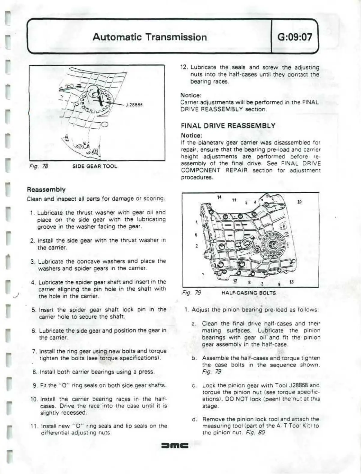
Fig. 79 HALF-CASING BOLTS
5. Insert the spider gear shaft lock pin in the
carrier hole to secure the shaft.
6. Lubricate the side gear and position the gear in
the carrier.
7. Install the ring gear using new bolts and torque
tighten the bolts (see torque specifications).
8. Install both carrier bearings using a press.
9. Fit the "0" ring seals on both side gear shafts.
10.
Install the carrier bearing races in the half-
cases. Drive the race into the case until it is
slightly recessed.
11.
Install new "0" ring seals and lip seals on the
differential adjusting nuts.
1.
Adjust the pinion bearing pre-load as follows:
a. Clean the final drive half-cases and their
mating surfaces. Lubricate the pinion
bearings with gear oil and fit the pinion
gear assembly in the half-case.
b. Assemble the half-cases and torque tighten
the case bolts in the sequence shown.
Fig. 79
c. Lock the pinion gear with Tool J28868 and
torque the pinion nut (see torque specific-
ations). DO NOT lock (peen) the nut at
this
stage.
d.
Remove the pinion lock tool and attach the
measuring tool (part of the
A
T Tool Kit) to
the pinion nut. Fig. 80
 Loading...
