Steering
H:04:01
STEERING COLUMN IGNITION LOCK ASSEMBLY
REMOVAL
1.
Remove driver's knee pads from both sides of
the steering column by removing four (4) nuts
securing each knee pad.
2.
Remove instrument cluster support bracket
from cluster.
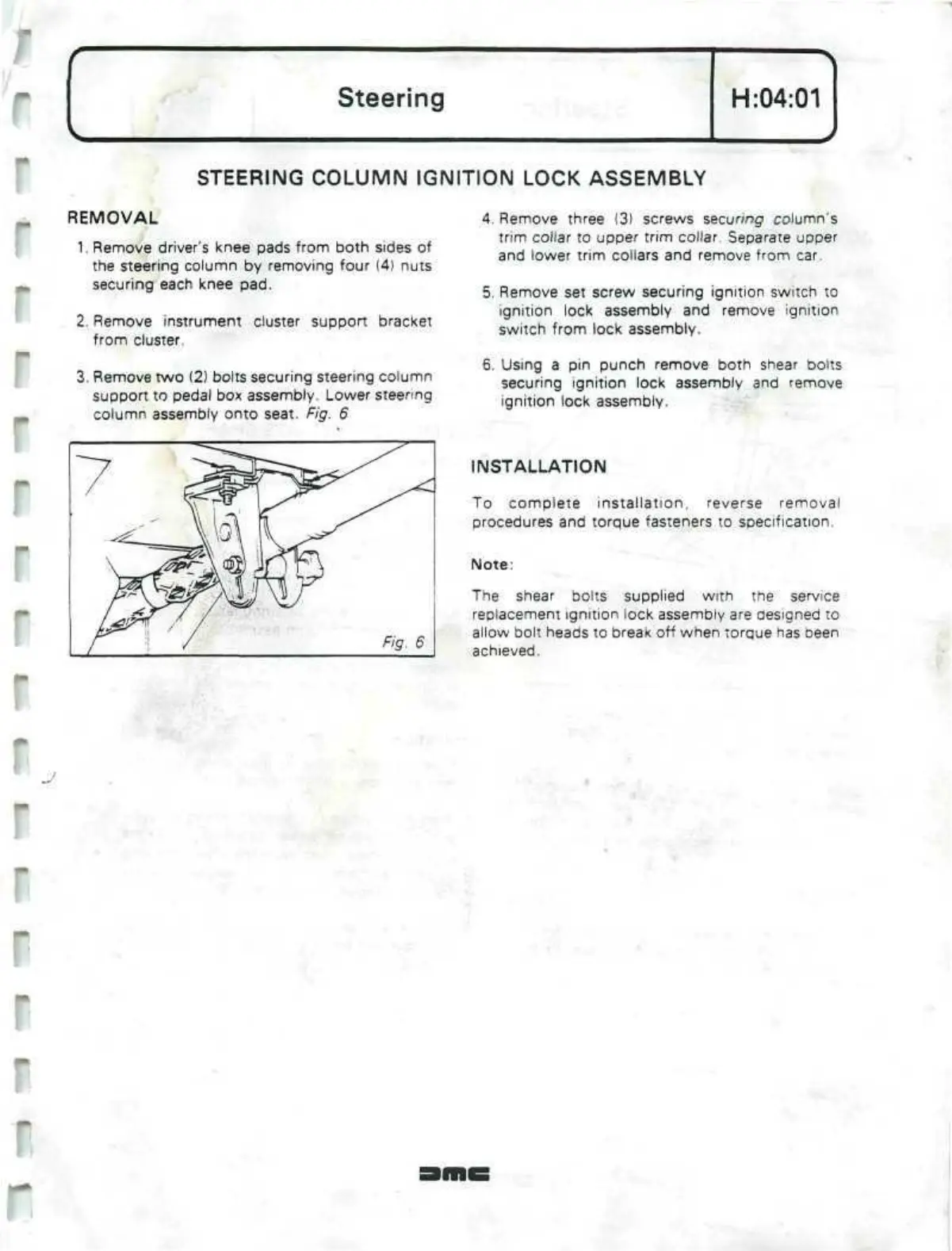
3. Remove two (2) bolts securing steering column
support to pedal box assembly. Lower steering
column assembly onto seat. Fig. 6
4.
Remove three (3) screws securing column's
trim collar to upper trim collar. Separate upper
and lower trim collars and remove from car.
5. Remove set screw securing ignition switch to
ignition lock assembly and remove ignition
switch from lock assembly.
6. Using a pin punch remove both shear bolts
securing ignition lock assembly and remove
ignition lock assembly.
INSTALLATION
To complete installation, reverse removal
procedures and torque fasteners to specification.
Note:
The shear bolts supplied
with
the service
replacement ignition lock assembly are designed to
allow bolt heads to break off when torque has been
achieved.
J
r
r
 Loading...
