H:03:02
Steering
5. Position and secure ignition lock assembly to
column with shear bolts.
Note:
Shear bolts are designed to allow
bolt
heads to
break off when torque has been achieved.
6. Position and secure multifunction switch to
steering column.
Note:
The "nub" on the turn signal cancelling cam
must be pointing towards the turn signal lever
in order to operate properly.
7. Connect steering column electrical harnesses.
8.
Position
and secure both driver's instrument
column knee pads.
9. Position and secure steering wheel to steering
column and torque to specification. Install
steering wheel trim pad.
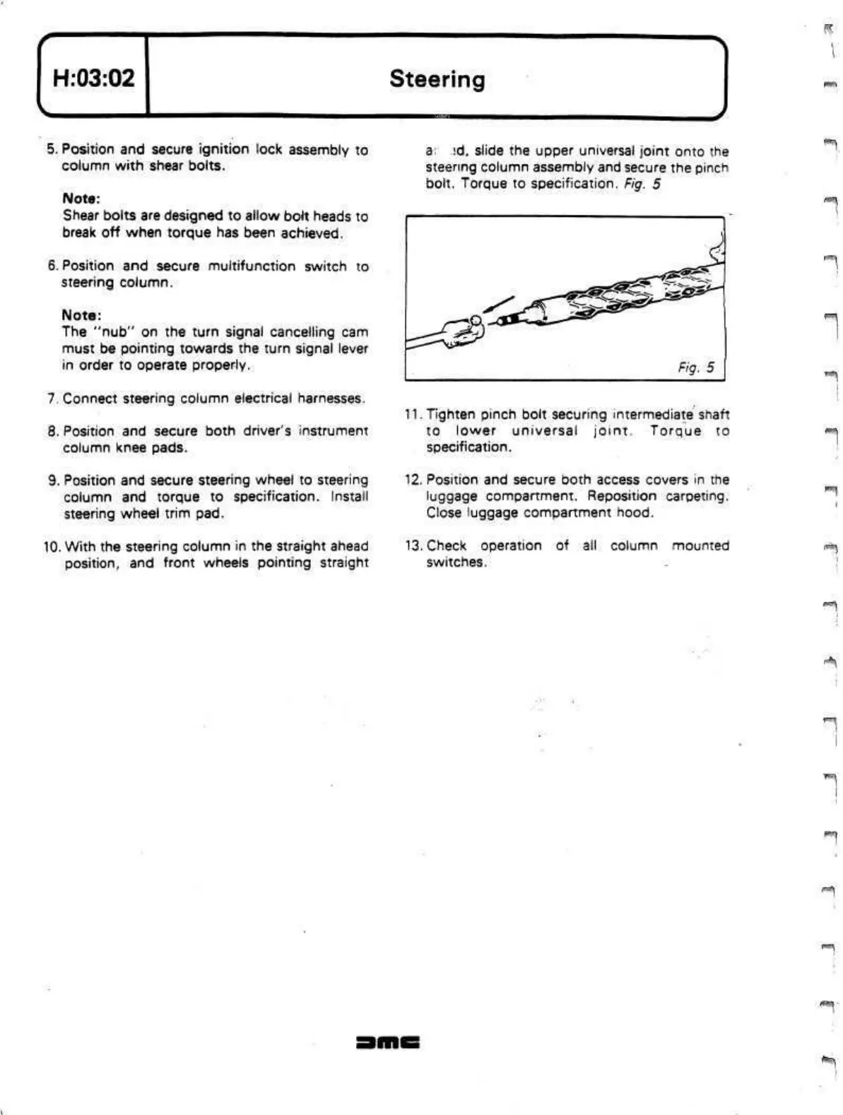
10.
With the steering column in the straight ahead
position,
and front wheels pointing straight
a.
^d,
slide the upper universal joint onto the
steering column assembly and secure the pinch
bolt. Torque to specification. Fig. 5
11.
Tighten pinch bolt securing
intermediate
shaft
to lower universal joint. Torque to
specification.
12.
Position and secure both access covers in the
luggage compartment. Reposition carpeting.
Close luggage compartment hood.
13.
Check operation of ail column mounted
switches.
 Loading...
