r
Steering
H:08:01
TIE ROD END - ONE OR BOTH
r
r
r'
r
r
r
REMOVAL
1.
Raise car on hoist and remove tyre and wheel
assembly (or assemblies).
2.
Remove tie rod end to steering knuckle nut(s)
and separate tie rod end(s) from steering
knuckie(s)
with appropriate
tool.
3. Remove
tie
rod end(s) from tie rod(s).
INSTALLATION
1.
Install replacement tie rod end(s) on tie rod(s)
2.
Position and secure tie rod end(s) to steering
knuckle(s) and grease tie rod end(s)
via its
fitting.
Torque nut(s) to specification.
3. Position and secure tyre and wheel assembly
(or assemblies) and torque to specification.
4.
Lower car, and with car at setting height:
(a) Front cross member to ground 140 mm
(5.5 inches).
(b) This should be checked bv means of a
wooden block depth to be 140 mm
(5.5
inches) which should be placed beneath
the front cross member (it may be
necessary to lift the front of the vehicle
or load the luggage compartment to ensure
that the chassis cross member rests on the
block.
Ic)
Check toe-in and adjust track.
(d) Ensure the steering wheel is in the dead
ahead position. Ensure all road dirt is
removed from the threads of the track rod
arms.
With the aid of suitable tracking
equipment check wheel alignment.
ANGULAR WHEEL ALIGNMENT TOE IN
y
2
DEGREE (PER WHEEL) +0 -10
minutes.
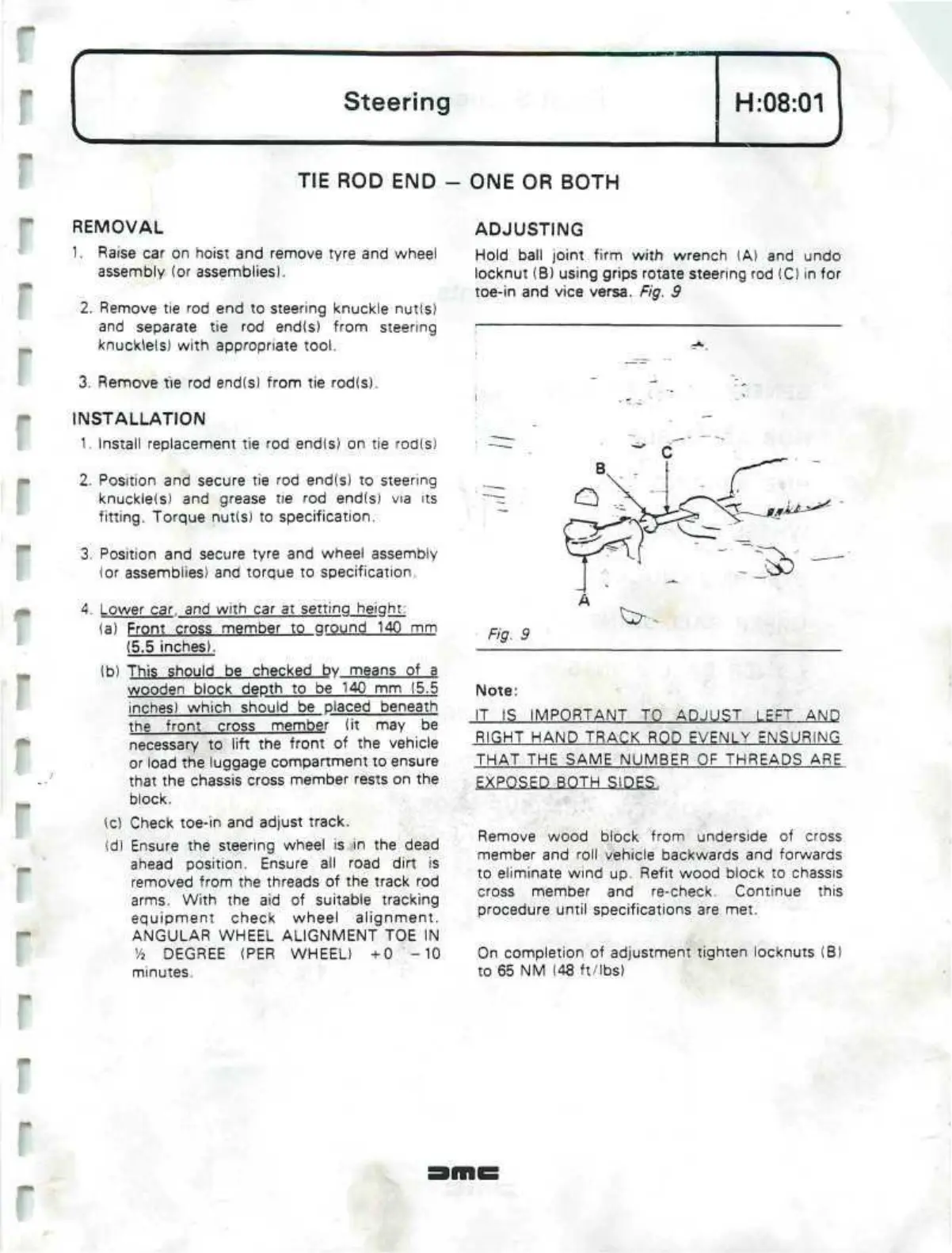
ADJUSTING
Hold ball joint firm with wrench (A) and undo
locknut (B) using grips rotate steering rod (C) in for
toe-in and vice versa. Fig. 9
Fig. 9
Note:
IT IS IMPORTANT TO ADJUST LEFT AND
RIGHT HAND TRACK ROD EVENLY ENSURING
THAT THE SAME NUMBER OF THREADS ARE
EXPOSED BOTH SIDES.
Remove wood block from underside of cross
member and roll vehicle backwards and forwards
to eliminate wind up. Refit wood block to chassis
cross member and re-check. Continue this
procedure until specifications are met.
On completion of adjustment tighten locknuts (B)
to 65 NM (48 ft/lbs)
 Loading...
