Electrical System and Instruments
M.01.03
J
5. Remove Screws (15) and withdraw Vacuum
Valve
(16),
withdraw Coil Magnet (12) and
Base Plate (17) as an assembly.
6. Remove three Screws (11) and remove Coil
Magnet (12). Take care not to lose the Rotor
Key (13).
ELECTRONIC CONTROL UNIT
(E.C.LU
- Fig. 5
The E.C.U. module controls the operation of the
ignition coil and determines the proper dwell angle.
The module is a sealed component and must be
replaced as a unit when confirmed as the cause of
ignition breakdown. The module monitors engine
operation by the varying voltage pulses
it
receives
from the pulse generator in the Distributor. This
then converts the signal received which breaks this
current suddenly to obtain induced H.T. current at
the coil output terminal.
This H.T. current is sent to each spark via a rotor
arm in the same way as in the conventional
distributor.
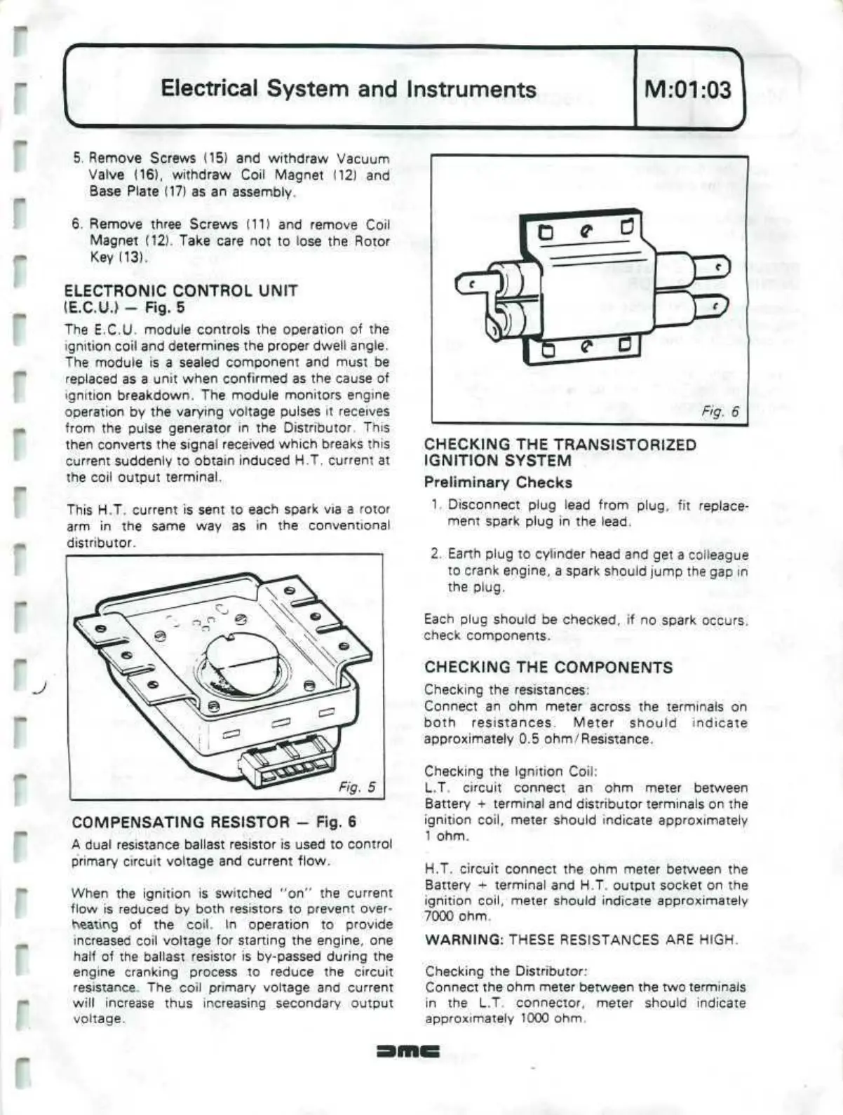
COMPENSATING RESISTOR - Fig. 6
A dual resistance ballast resistor is used to control
primary circuit voltage and current flow.
When the ignition is switched "on" the current
flow is reduced by both resistors to prevent over-
heating of the
coil.
In operation to provide
increased coil voltage for starting the engine, one
half of the ballast resistor is by-passed during the
engine cranking process to reduce the circuit
resistance. The coil primary voltage and current
will increase thus increasing secondary output
voltage.
CHECKING THE TRANSISTORIZED
IGNITION SYSTEM
Preliminary Checks
1.
Disconnect plug lead from
plug,
fit replace-
ment spark plug in the
lead.
2.
Earth plug to cylinder head and get a colleague
to crank engine, a spark should jump the gap
in
the
plug.
Each plug should be checked, if no spark occurs.
check components.
CHECKING THE COMPONENTS
Checking the resistances:
Connect an ohm meter across the terminals on
both resistances. Meter should indicate
approximately 0.5
ohm/Resistance.
Checking the Ignition
Coil:
L.T. circuit connect an ohm meter between
Battery + terminal and distributor terminals on the
ignition
coil,
meter should indicate approximately
1 ohm.
H.T. circuit connect the ohm meter between the
Battery + terminal and H.T. output socket on the
ignition
coil,
meter should indicate approximately
7000 ohm.
WARNING: THESE RESISTANCES ARE HIGH.
Checking the
Distributor:
Connect the ohm meter between the two terminals
in the L.T. connector, meter should indicate
approximately 1000 ohm.
 Loading...
