;:'
fff®,
p^7>
Electrical System and Instruments
MOTOROLA ALTERNATOR
r
i**W^
rt^Tt
•pfj=l
BUILT-IN REGULATOR
CHECKING OUTPUT
1.
Connect a voltmeter across the battery posts.
2.
Read off battery voltage.
3. Start engine and accelerate until the voltmeter
needle remains steady on the regulated
voltage.
4.
The voltage should read between 13.5 v and
15.0
v..
THE INSTRUMENT PANEL HAS A RED
WARNING LIGHT WHICH WORKS AS
FOLLOWS:
1.
On switching on the ignition it is illuminated.
2.
As soon as engine starts it goes out.
3. If it is illuminated when the engine is running
there is a charging fault.
If the warning light fails to be illuminated on
switching on ignition, check the following:
1.
That no connectors are loose or disconnected.
2.
That the bulb has not blown (touch earth wire
with the regulator connector to check):
If the warning light is illuminated while engine is
running there is a charging fault which may be due
to:
1.
Broken alternator belt.
2.
Broken charging wire.
3. Alternator internal fault (rotor, stator, diodes or
brushes).
4.
Regulator fault.
MOTOROLA ALTERNATOR REMOVING
1.
Disconnect battery.
2.
Disconnect wires to alternator.
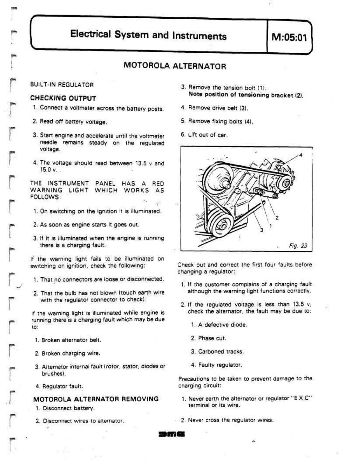
3. Remove the tension bolt (1).
Note position of tensioning bracket (2).
4.
Remove drive belt (3).
5. Remove fixing bolts (4).
6. Lift out of car.
Fig. 23
Check out and correct the first four faults before
changing a regulator:
1.
If the customer complains of a charging fault
although the warning light functions correctly.
2.
If
the regulated voltage is less than 13.5 v,
check the alternator, the fault may be due to:
1.
A defective diode.
2.
Phase cut.
3. Carboned tracks.
4.
Faulty regulator.
Precautions to be taken to prevent damage to the
charging circuit:
1.
Never earth the alternator or regulator "E X C"
terminal or its wire.
2.
Never cross the regulator wires.
 Loading...
