IM:10:02
Heating and Air Conditioning
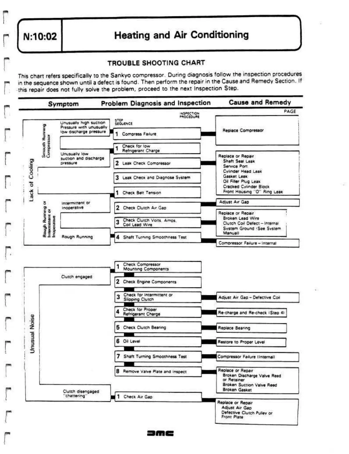
TROUBLE SHOOTING CHART
This chart refers specifically to the Sankyo compressor. During diagnosis follow the inspection procedures
in the sequence shown until
a
defect is found. Then perform the repair in the Cause and Remedy Section. If
this repair does not fully solve the problem, proceed to the next Inspection Step.
WUfff
r
I™"*)
05
C
0
o
•
CJ
o
(0
3
V)
3
C
Symptom
Problem Diagnosis and Inspection Cause and Remedy
Unusually
high
suction
Pressure
with
unusually
low discharge pressure
3
5
Unusually low
suction and discharge
pressure
3 S
>
cc =
=
Intermittent or
Inoperative
Rough Running
Clutch engaged
Clutch disengaged
"chattering"
STEP
SEQUENCE
INSPECTION
PROCEDURE
PAGE
1 Compress Failure
Check for low
Refrigerant Charge
2 teak Check Compressor
3
teak
Check and Diagnose System
1 Check Belt Tension
2 Check Clutch
Air
Gap
«
Check Clutch Volts.
Amps.
J
Coil Lead Wire
4 Shaft Turning Smoothness Test
m
Check Compressor
' Mounting Components
2 Check Engine Components
Check for Intermittent or
Slipping Clutch
A
Check for Proper
2
Refrigerant Charge
5 Check Clutch Bearing
6 Oil Level
7 Shaft Turning Smoothness Test
8 Remove Valve Plate and Inspect
1 Check Air Gap
M
Replace Compressor
Replace or Repair
Shaft Seal Leak
Service Port
Cylinder Head Leak
Gasket Leak
Oil Filler Plug Leak
Cracked Cylinder Block
Front Housing "0" Ring Leak
Adjust
Air
Gap
Replace or Repair
Broken Lead Wire
Clutch Coil Oefect -
Internal
System Ground
'See Svstem
Manual)
Compressor Failure - Internal
Adjust Air Gap - Defective
Coil
Re-charge and Re-check (Step
4)
Replace Bearing
Restore to Proper Level
Compressor Failure (Internal)
Replace or Repair
Broken Discharge Valve Reed
or Retainer
Broken Suction Valve Reed
Broken Gasket
Replace or Repair
Adjust Air Gap
Defective Clutch Pulley or
Front Plate
 Loading...
