The preceding Trouble Shooting Chart is a useful
tool for systematically pursuing a course of repair.
The following are specific inspection procedures:
LEAK CHECK
(T)
means the compressor can be repaired.
(NR)
means non-repairable. The compressor will
have to be replaced.
Visual
Seeping oil does not necessarily indicate leaking
refrigerant. Look for the following problems:
• Shaft seal area seeping oil. Feel under seal area
between clutch and compressor.
(£)
• Dislocation of front housing "0" ring
(protruding
section),
(NR)
• Oil around cylinder head (gasket, service port,
fittings).
(T)
• Oil around filler hole. "0"
ring.
©
Stripped
threads,
(NR)
• Oil around crack in cylinder block.
@
General
Always clean away all oil, grease, etc. and blow
away residual refrigerant before starting detection.
Refer to System or Supplier Manuals for the
proper techniques to be used for Halide or
*J
"Electronic" Leak Detectors.
Halide Flame Detectors — Any portion of the
compressor, including the seals, which shows a
leak indication on the flame will require leak repair.
"Electronic"-Shop-Type
Detectors* — In the
seal area, set the instrument
%
to
%
range above
maximum sensitivity. All other portions of the
compressor — set the detector at maximum
sensitivity.
(*Detectors
with a minimum leak rate
of
V4
to 1 02. per year.)
"Soap Bubble" Detection — Any bubbles on any
portion of the compressor indicate a leak requiring
repair.
Note:
A useful device for finding a shaft seal leak,
while the compressor is installed. Bend a 90°
angle,
making about a
3
A"
leg, on a 12" piece of
%"
copper tube. Insert the straight end into the
detector hose. The "leg" can easily be inserted
into one of the clutch front plate holes.
OIL CHECK PROCEDURES
Whenever a system component has been
replaced or there is an obvious oil leak, iollow
the procedures below . . . after repairs have
been made.
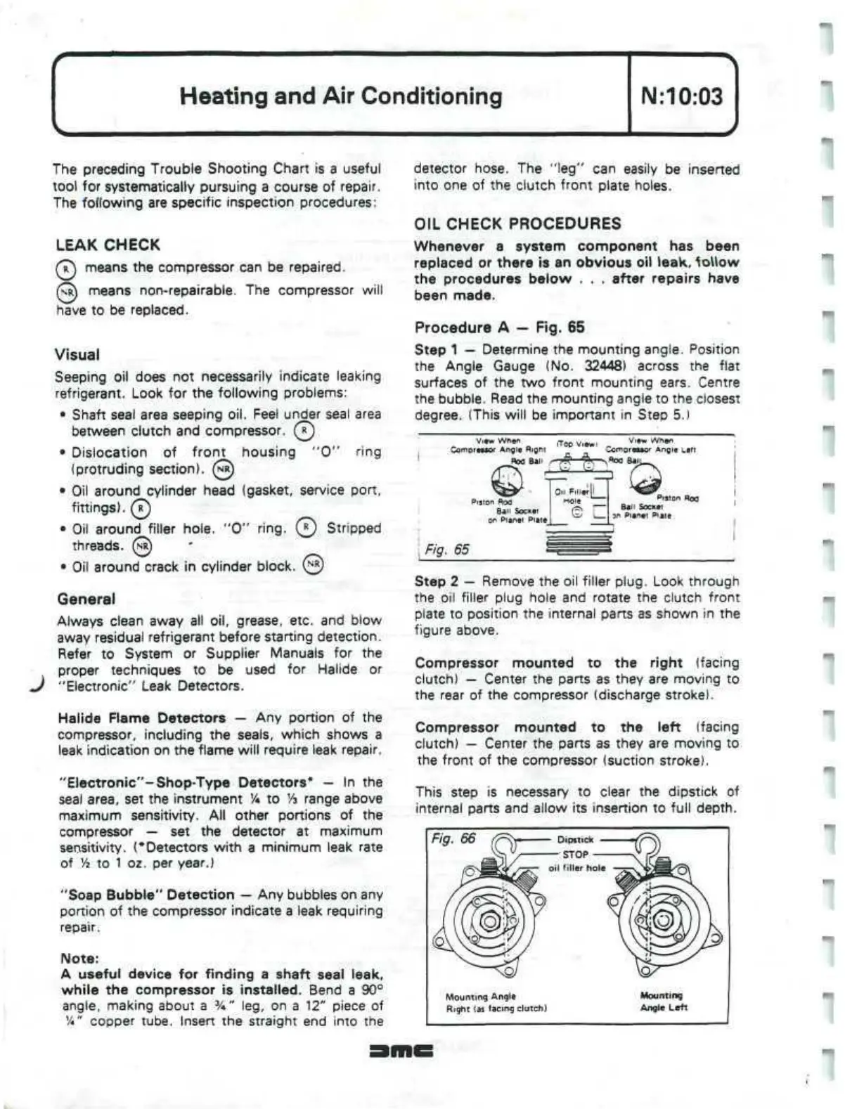
Procedure A — Fig. 65
Step 1 — Determine the mounting angle. Position
the Angle Gauge (No. 32448) across the flat
surfaces of the two front mounting ears. Centre
the bubble. Read the mounting angle to the closest
degree. (This will be important in Step 5.)
View
When
Compreaaor
Angle
Rigni
Rod Ban
(Too
View
View
When
Comnre»tor
Angle
Left
^Roo
BalJ.
Puton Roo
Ban Socket
on Planet
E
Filler
[i_
loie
Piston Rod
Ball Socket
an
Planet Plate
Fig. 65
Step 2 — Remove the oil filler
plug.
Look through
the oil filler plug hole and rotate the clutch front
plate to position the internal parts as shown in the
figure above.
Compressor mounted to the right (facing
clutch) — Center the parts as they are moving to
the rear of the compressor (discharge stroke).
Compressor mounted to the left (facing
clutch) — Center the parts as they are moving to
the front of the compressor (suction stroke).
This step is necessary to clear the dipstick of
internal parts and allow its insertion to full depth.
Fig. 66
Mounting Angle
Right (as facing clutch)
Mounting
Angle Left
 Loading...
