W&\
rrw\
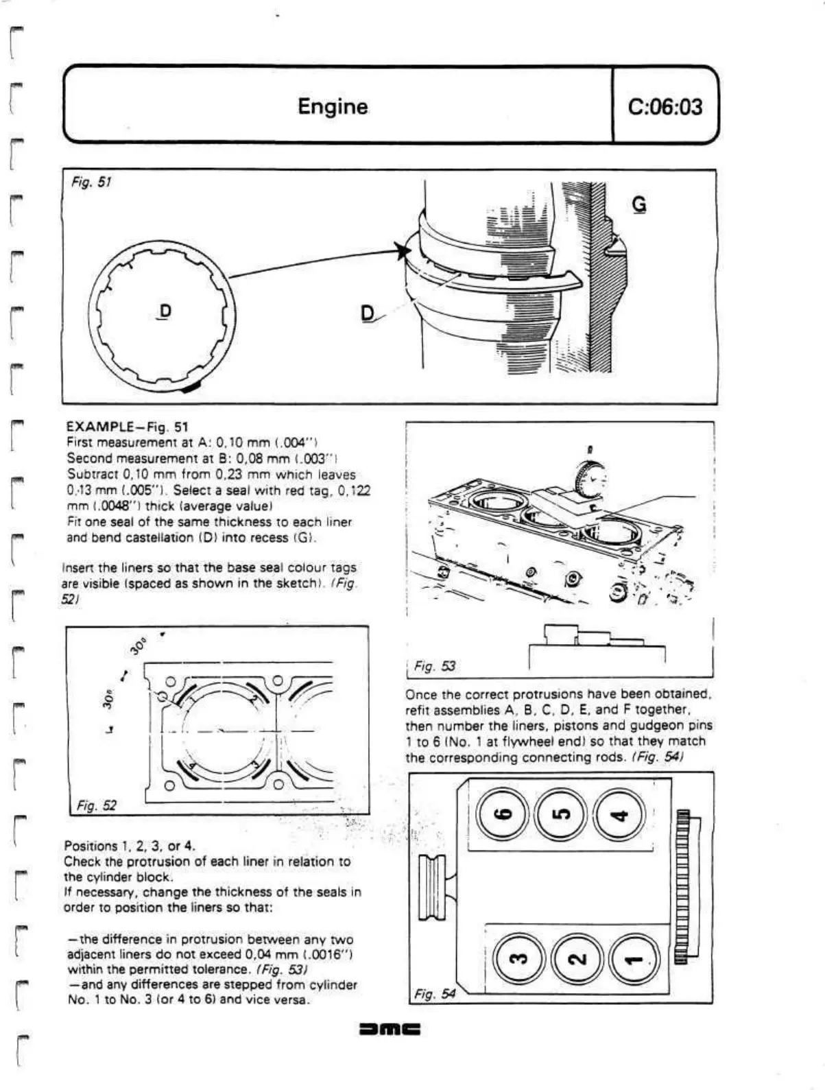
EXAMPLE-Fig.
51
First measurement at A: 0,10 mm
(.004")
Second measurement at B: 0,08 mm
(.003")
Subtract 0,10 mm from 0,23 mm which leaves
0/13
mm (.005"). Select a seal with red tag, 0,122
mm (.0048") thick (average value)
Fit one seal of the same thickness to each liner
and bend castellation (D) into recess (G).
Insert the liners so that the base seal colour tags
are visible (spaced as shown in the sketch). (Fig.
52)
-P
^EE^*^
Fig. 52
Positions 1, 2, 3, or 4.
Check the protrusion of each liner in relation to
the cylinder block.
If necessary, change the thickness of the seals in
order to position the liners so that:
—the difference in protrusion between any two
adjacent liners do not exceed 0,04 mm (.0016")
within the permitted tolerance. (Fig. 53)
— and
any differences are stepped from cylinder
No.
1
to No. 3 (or 4 to 6) and vice versa.
Once the correct protrusions have been obtained,
refit assemblies A, B, C, D, E, and F together,
then number the liners, pistons and gudgeon pins
1 to 6 (No. 1 at flywheel end) so that they match
the corresponding connecting rods. (Fig. 54)
 Loading...
