NOTE:
The arm has LH and RH threaded ends to
assist adjustment.
The LH threaded end is identified by a groove (7)
on the ball joint. Disconnect the HT wires from
the distributor.
Free the lower casing rearwards to clear the air
intake elbow rings and lift it at the back to pass
over the distributor cap. Remove the lower casing
and disconnect the vacuum pipes on the
distributor.
REFITTING
Change all seals. There
is
a plastic seal at the
eibow
end of the air channel and an "0" ring at
the lower casing end
in
the connecting rings.
Connect up the vacuum pipes.
Offer up the casing.
Screw
in
bolt (4) first to enable capscrews (3)
to line up with their holes.
Tighten bolt (4) then capscrews (3). (Fig.
118)
Re-connect
The HT wires to the distributor cap
All fuel unions
The
idle
speed air pipe, after greasing the "0"
ring
in the lower casing
The idle speed control
The throttle arm ball joint, locking
it
correctly
with
the clip (8) (Fig.
119)
INLET
AIR MANIFOLD
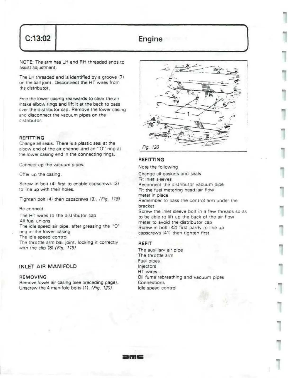
REMOVING
Remove lower air casing (see preceding page)
Unscrew the 4 manifold bolts (1). (Fig. 120)
Fig. 120
REFITTING
Note the following
Change all gaskets and seals
Fit inlet sleeves
Reconnect the distributor vacuum pipe
Fit the fuel metering head/air flow
meter in place
Remember to pass the control arm under the
bracket
Screw the inlet sleeve bolt in a few threads so as
to be able to lift up the back of the
air
flow
meter to avoid the distributor cap
Screw in bolt (42) first parrly to line up
capscrews (41) then tighten first
REFIT
The auxiliary air
pipe
The throttle arm
Fuel pipes
Injectors
HT wires
Oil fume rebreathing and vacuum pipes
Connections
Idle speed control
 Loading...
