5.1 Maintenance Mode
5.2 Battery Replacement
MAINTENANCE
Every 45 days the DC UPS automatically self tests the battery to determine its remaining useful life. No user interven-
tion is needed. If the unit detects a failed battery, the “Replace Battery” LED indicator on the unit will illuminate.
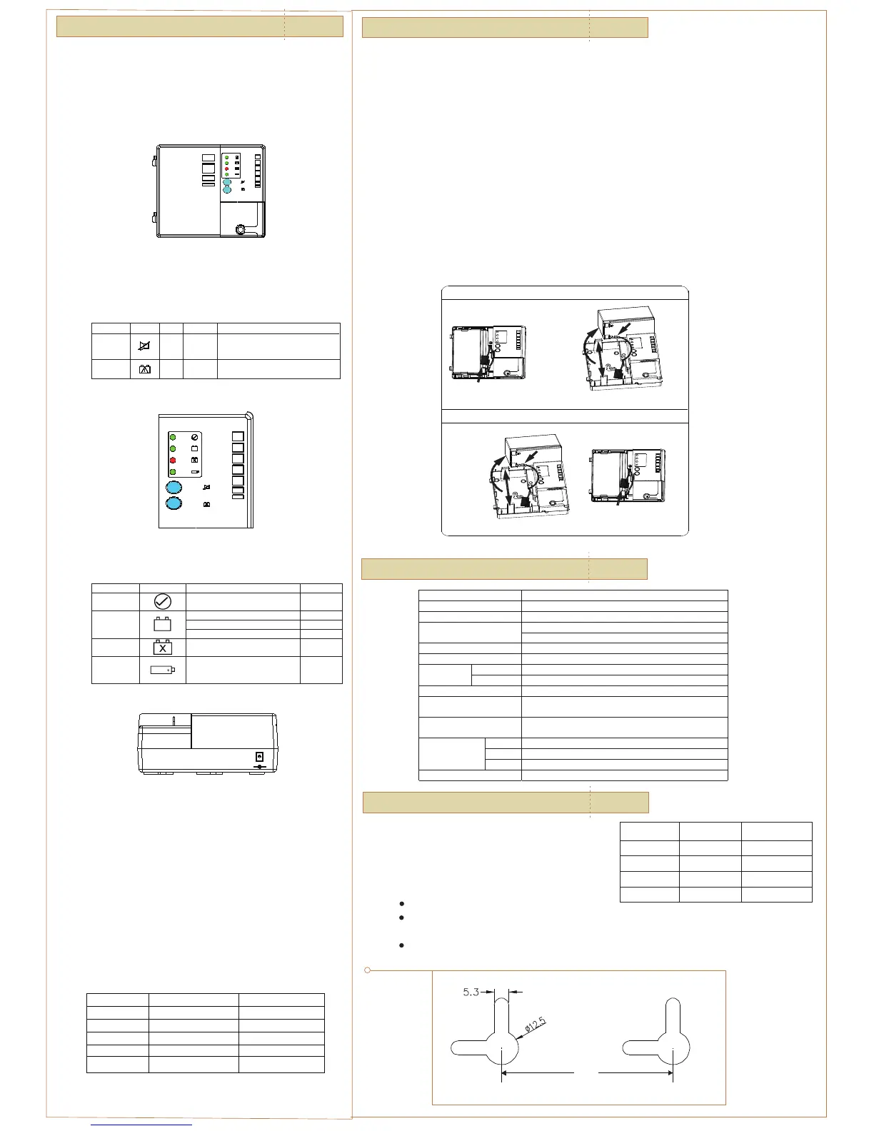
1. Open the front cover of the DC UPS.
2. Push the tabs retaining the battery, one above and one below, outward and remove the battery.
3. Disconnect the jack connecting the battery harness to the DC UPS.
4. Disconnect the battery harness from the battery terminals.
5. Reconnect the battery harness to a new, identical type battery.
6. Reconnect the jack of the battery harness to the DC UPS.
7. Push the battery retaining tabs outward and insert the battery into the DC UPS. Make sure the wires of
the battery harness are free and not pinched by the battery or the door.
8. Close the door of the DC UPS.
| 05
SPECIFICAT I O N S
| 06
Figure 4: Front Panel LED and Controls
OPERAT I O N
The DC UPS starts once the AC power cord is plugged in. Connecting
the battery only can not start the power supply, the AC supply must be
connected. Once the power supply has started the unit will operate on
the battery if the AC supply voltage should fail or the power cord be
disconnected.
| 04
Your UPS contains a Non-spill able Sealed Lead Battery.
On the battery, you will find the battery name.
Please refer to the chart below for recycling information.
The Cold Start button will reconnect the battery to discharge mode
when user replace another fresh battery on AC outage.
Four status LEDs are displayed on the front panel of the DC UPS. The
operation of the DC UPS can be assessed using these LEDs and Table 3.
Figure 5: DC UPS Front Panel LEDs
Table 4: Audible Alarm Actions
The Auxiliary Power Connection is a connection point for customer-
supplied DC input voltage (20VDC maximum). When an Auxiliary power
source is plugged into the DC UPS, the equipment will be supplied
from the auxiliary source. The battery inside the DC UPS will not charge
through the auxiliary power but will charge if AC power is present.
The auxiliary port is a male coaxial power style connector (3.5mm OD;
1.3mm ID), positive connected to the center pin.
The auxiliary power source can remain attached to the DC UPS
indefinitely without any adverse affect to the DC UPS, battery, or
auxiliary power source. If the DC UPS has stopped operating due to a
long AC power failure and complete depletion of the DC UPS battery,
the DC UPS will start to operate once an Auxiliary supply is plugged in
the auxiliary port.
Function Symbol Type Location Function
Push
Push
Front
Cover
Front
Cover
Reconnect the battery dischange when
user replace another fresh battery.
Press and hold the Alarm Silence button
for 1-2 seconds to mute/ restore alarm.
Muting remains effective for 24 hours.
Table 2: Customer Button Operation
TYPE Symbol Condition Alarm Action
System Status
System ON and normal, idle or discharging ON GREEN
Battery Charging OFF
Battery discharging ON GREEN
Battery Power
<45% capacity remaining FLASH GREEN
Replace Battery
Battery failed self test ON RED
Auxiliary Power
Aux source connected to unit. ON GREEN
Table 3: LED Indicators
AUXILIARY
Figure 6: Battery Replacement
SAFETY I N F O R M ATION
| 07
One user control is present in the form of two blue buttons on the
front cover of the DC UPS.
BATTERY
POWER
AUXILIARY
REPLACE
POWER
BATTERY
STATUS
SYSTEM
ALARM
SILENCE
Battery Removal Instructions:
Battery Installation Instructions:
(1)Disconnect "+" Terminal
(3)Connect "+" Terminal
(1)Connect "-" Terminal
(2)Push Tabs
Outwards
& Install
Battery
(3)Disconnect "-" Terminal
(2)Push Tabs
Outwards
& Remove
Battery
Note: Wall mount screws distance
Battery Name
Recycling
Inside the USA
Recycling Outside
the USA
BB Battery (800) 278-8599 N/A
CSB Battery (800) 738-7372 1 (817) 244-4415
VISION Battery (877) 730-2877 N/A
RITAR Battery (800) 273-8599 N/A
POWER
AUXILIARY
REPLACE
BATTERY
BATTERY
POWER
STATUS
SYSTEM
ALARM
SILENCE
TYPE Condition Buzzer
Low Battery <45% capacity remaining
Beeps 4 times/minute
On Battery Battery being discharged None
Battery Missing
No battery installed or
battery disconnected
None
Replace Battery Battery self test fails Beeps once every 15 miutes.
Input Power Failure Loss of input power
Beeps when power loss
START
COLD
START
COLD
ALARM
SILENCE
START
COLD
4.1 Start-Up
4.2 Controls
4.3 Operational LEDs
4.4 Auxillary Power Connection
4.5 Audible Alarm
Table 2 describes the funtions of the two blue buttons.
Note: During an AC outage if the battery in the UPS needs to be replaced, you must use the Cold Start button to
restart the UPS after the battery is replaced. First replace the existing battery using the instructions already
provided in this manual, and then reconnect the fresh battery. Second you must press the Cold Start button
to restart the UPS (only needed during an AC outage).
Internal battery voltage is 12V DC.
The unit is intended for installation in a controlled environment
(temperature controlled, indoor area free of conductive contaminants).
The battery used is Sealed Lead Batteries. The battery must be recycled.
7.2
CAUTION!
Model DUPS-1232/1232G
AC Input 90 to 264 VAC, 50/60 Hz
Input Connector IEC 320/C5 3-wire
USA model: NEMA 5/15 8 ft @ 3-prong / with GND
Input Cord
GR/ UK/ AU model: 6 ft @ 3-prong / with GND
Auxiliary Input 12.5 to 20 VDC (Alkaline Battery)
DC Output 13.3 VDC typical
Temperature –20°C to 50°C
Environmental
Humidity Operation: 5% to 95%, non-condensing
Battery Type 12V/ 7Ah Sealed Lead Acid Battery
Safety
UL 60950-1, CAN/CSA-C22.2 No. 60950-1, IEC 60950-1, EN
60950-1,CE,
EMC
FCC Part15, EN55022(CISPR 22) Class B, C-Tick (AS/ NZS
CISPR 22) Class B, EN 300386-1
Height 178.9 mm/ 7.04”
Width 210 mm/ 8.26”
Dimensions
Depth 78 mm/ 3.07”
Weight 3.34Kg/ 7.42lb (net)
7.1
Recycling Information
63.5
 Loading...