SM800 DELTA ELEKTRONIKA BV
October 2007 DESCRIPTIONS Page 3 - 7
32) VOLT AGE AND CUR RENT LIMIT
The Volt age and Cur rent Lim its main tain the out put to a safe pre set value.
They do not trip, so no re set ting is needed af ter a fault. It can be very handy to
have hard ware lim its when the power sup ply is pro grammed.
The lim its can eas ily be set by press ing the DIS PLAY LIM ITS but ton and
ad just ing the limit po ten ti om eters with a screw driver. The LED’s next to the
limit potmeters in di cate the ac tiv ity of each limit, also the LIM-sta tus out put will
be "1".
The Volt age Limit will pro tect your cir cuit from un wanted high volt ages. A high
out put volt age could be caused by ac ci den tal in ter rup tion of leads, ac ci den tally
turn ing up the volt age potmeter, a pro gram ming er ror or a de fect in the power
sup ply. The Volt age Limit cir cuit uses a sep a rate volt age di vider con nected di -
rectly to the out put ter mi nals.
The Cur rent Limit pro tects your cir cuit from un wanted high cur rents.
Note: In the Autoranging units the limit cir cuits are also used as "range lim its".
This can be con fus ing. Ex am ple: an SM70-AR-24 op er at ing in the range above
35 V will au to mat i cally re duce the limit set ting to a max i mum of 12 A.
Warn ing: if this unit op er ates in the range be low 35V, this set ting is 24 A !
Take care the out put ca bling and the load can with stand such a high cur rent or
oth er wise re duce the limit set ting to a lower value.
33) PO TEN TI OM E TERS
° Stan dard: - CV and CC po ten ti om eters with knobs at front panel,
Volt age Limit and Cur rent Limit po ten ti om eters with
screw driver ad just ment at the front panel.
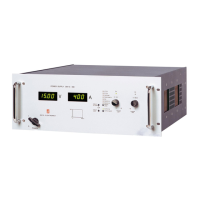
° Op tion P001: - Screw driver ad just ment for CV, CC, Volt age Limit and
Cur rent Limit at the front panel (fig. 3 - 22).
34) COOLING
A low noise blower cools the unit. The speed of the fan de pends on the tem per -
a ture of the in ter nal heatsink. Normally at 50 °C am bi ent and full load the fan
will not work at full speed.
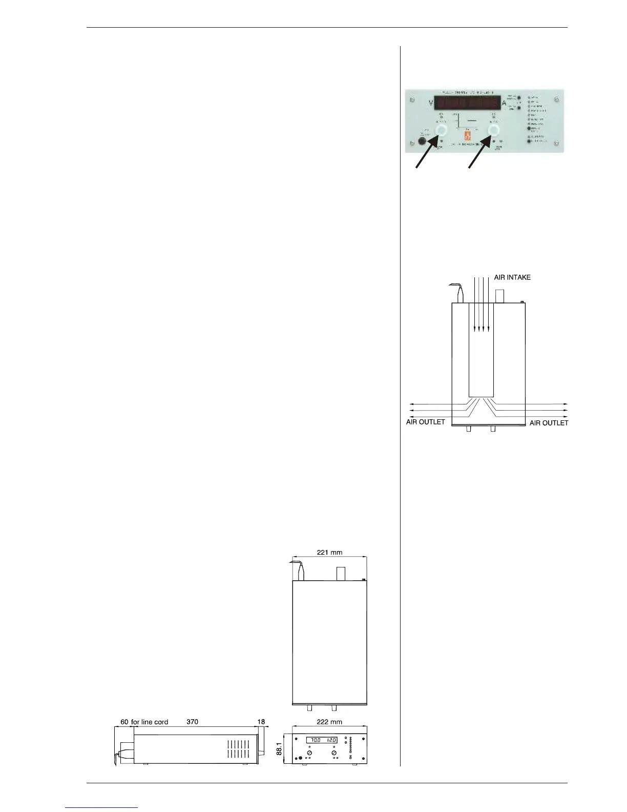
A spe cial fea ture is that the fan blows through a tun nel where the heatsink is
sit u ated, the del i cate con trol cir cuitry is sep a rated and will not be in the air flow
path (see fig. 3 - 23).
Be cause the air en ters at the rear side and ex its at the left and right side, it is
pos si ble to stack the power sup plies, no dis tance be tween the units is re quired.
Be cause only one of the ven ti la tion open ings at the left side or right side should
be free, it is pos si ble to put two units in par al lel in a rack.
For long life the tem per a ture of the air en ter ing on the left side, should be
be low 35 °C un der nor mal con di tions. Un der ex treme conditions it should be
be low 50 °C.
Note: The con trol cir cuit makes the fan start in a pul sat ing mode, dur ing which
pe riod it can pro duce a high pitched sound. This is nor mal.
35) DI MEN SIONS
fig. 3 - 22
Screw driver ad just ment at front panel.
Be hind the plas tic caps, the CV- and
CC-set tings can be ad justed
with a screw driver.
fig. 3 - 23
The fan blows through an in ter nal tun nel,
where the heatsink is sit u ated.
Al ways take care to have at least one air
out let un ob structed.
 Loading...