SM800 DELTA ELEKTRONIKA BV
October 2007 OPERATING MAINTENANCE TROUBLE SHOOTING CALIBRATING Page 4 - 2
• To avoid hum or noise, the pro gram ming ca ble may have to
be twisted in some cases.
• To pro gram the unit by cur rent in stead of volt age, sim ply use a
par al lel re sis tor as a cur rent to volt age con verter.
• Pressing the DIS PLAY SET TINGS but ton will show the pro -
grammed val ues for CV and CC.
• CAU TION: The an a log in puts are not iso lated from the out put.
The Ø of the prog. in put (pin 1) is in ter nally con nected to the
S–, the S– is con nected to the neg a tive out put. To pro tect the
in ter nal wir ing a 650 mA self-resetting fuse is con nected in se -
ries (F27_1 on P647). To avoid earth loops, use an iso lated
pro gram ming source. If this is not pos si ble see next para -
graph 4), for us ing the op tional ISO AMP CARD.
4) AN A LOG PRO GRAMMING WITH ISO AMP CARD
• For pro gram ming via the ISO AMP CARD, set dipswitch 1 on
SW1 in the po si tion OFF.
• When the ISO AMP CARD is built in side the unit, CON E has
been covered. Use CON H in stead. The pin ning of CON H is
equal to the pin ning of CON E.
• For fur ther op er at ing in struc tions, see pre vi ous para graph 3) .
5) Ethernet / IEEE 488 / RS232 PRO GRAMMING
• Set dipswitch 1 on SW1 in po si tion OFF for pro gram ming with
the PSC-ETH, the PSC-488 or the PSC-232.
With dipswitch 1 in this po si tion, the sig nals Vprog (pin 11) and
Iprog (pin 3) are dis abled on CON E. All the other sig nals can
still be used. For Ethernet pro gram ming CON H must be used,
CON F and G can be used for the user in- and out puts.
For IEEE488 also CON H must be used for pro gram ming.
For RS232 pro gram ming CON F and G must be used.
• Set the unit in RE MOTE CV for volt age pro gram ming and/or in
RE MOTE CC for cur rent pro gram ming us ing the SCPI com -
mands (see man ual PSC) or us ing the RE MOTE/LO CAL but -
ton on the unit. Push this but ton sev eral times un til the right
set ting is ac ti vated. Set ting the unit in RE MOTE or LO CAL will
cause the out put to shut down to avoid ac ci den tal dam age to
the load. Turn it on again us ing the SCPI com mand or with the
OUT PUT ON/OFF but ton.
• Set dipswitch 1 on SW1 in po si tion ON to enable CON E again
for an a log pro gram ming.
In this po si tion volt age and cur rent pro gram ming on CON F
and H is dis abled. The other func tions and sig nals can still be
pro grammed and read back.
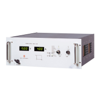
6) MON I TORING OUT PUTS
• The 5 V level is com pat i ble with most in ter faces.
• The mon i tor ing out puts can drive a me ter di rectly, fig. 4 - 4.
7) STATUS OUT PUTS
• The sta tus out puts have a sep a rate Ø con nec tion (pin 8) to
avoid un wanted off sets in the pro gram ming. This pin is pro -
tected with a 650 mA self re set ting fuse (F27_2 on P647).
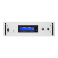
8) RE MOTE SENSING
• Re move the links on the SENSE BLOCK (on rear panel) and
con nect sense leads (thin shielded mea sur ing wires) to S+
and S– (see fig. 4 - 5 and fig. 4 - 6).
• With re mote sens ing the volt age on the load can be kept con -
stant. The volt age drop in the load leads will be com pen sated.
This fea ture is not rec om mended for nor mal use, be cause it
can eas ily give prob lems.
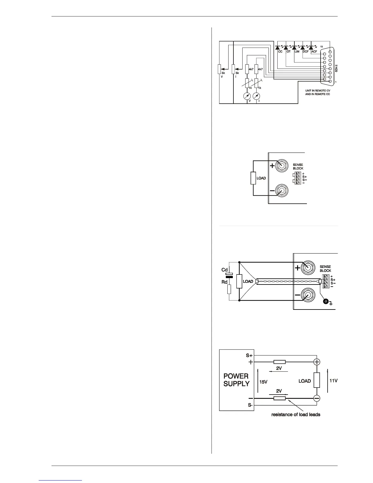
• Max. 2 V per load lead can be com pen sated. Note that the
volt age drop in the leads de creases the max. out put volt age
rat ing. In fig. 4 - 7 it can be seen that on a 15V power sup ply
only 11V will be avail able on the load when 2x 2V com pen sa -
tion is used.
• In or der to pre vent in ter fer ence, it is ad vis able to twist the
sense leads. To mini mise the in duc tance in the load leads
keep the leads close to each other. The in duc tance of the
loads leads could give a prob lem with pul sat ing loads. In this
fig. 4 - 4
Re mote con trol
fig. 4 - 5
Lo cal sens ing
fig. 4 - 6
Re mote sens ing with shielded wires
fig. 4 - 7
Re mote sens ing, volt age drop in load leads
subtracts from max. out put
 Loading...