SM800 DELTA ELEKTRONIKA BV
October 2007 DESCRIPTIONS Page 3 - 3
The Over Tem per a ture Sta tus or OT sta tus is "1" in case of an over tem per a ture,
the OT LED will be on and the out put shuts down. As a pre-warning the OT LED
starts to blink when the unit runs hot but the sit u a tion of over tem per a ture is not
reached yet. The sta tus will still be low when the LED is blink ing.
The Cur rent Con trol Sta tus or CC-status out put is "1" when the unit is in
CC-mode.
The Power Sink Over Load Sta tus or PSOL-status out put is "1" when the op tional
Power Sink is over loaded or over heated.
The AC-Fail Sta tus or ACF-sta tus out put is "1" when the in put volt age is be low
115V (peak, not rms) for more than 10 ms. Note that if you want the ACF-sta tus to
switch be fore the DCF-sta tus, the hold-up time has to be > 10 ms. This can be
achieved by re duc ing the load, see para graph 25) of this chapter.
The DC-Fail Sta tus or DCF-status out put is "1" when the out put volt age is ei ther
5% be low or above the set point.
When the unit is in CC-mode, DCF will al ways be "1", see pre vi ous para graph 7).
15) STATUS RE LAY OUT PUTS
The power sup ply has 2 sta tus re lay out puts, with each a change-over con tact.
They are con nected to con nec tor CON D. The pins 1, 2, 3 are con nected to the
DCF-re lay and pins 4, 5, 6 to the ACF-re lay (see fig. 3 - 10). Pin 1 is the up per
out put, clos est to SW1.
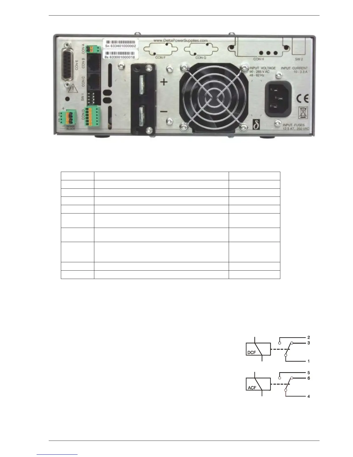
fig. 3 - 8 Location of out put ter mi nals and an a log pro gram ming con nec tor on the rear panel (stan dard unit)
CON A In ter lock Con nec tor para graph 18)
CON B Mas ter Connector for Mas ter / Slave op er a tion (out put) para graph 31)
CON C Slave Connector for Mas ter / Slave op er a tion (in put) para graph 31)
CON D Re lay Out puts, con tacts 1 - 6 ACF / DCF para graph 15)
CON E An a log Pro gramming Connector para graph 9)
CON F PSC-ETH, user inputs
PSC-232, from PC or pre vi ous PSC (op tional)
para graph 11)
CON G PSC-ETH, user outputs
PSC-232, to next PSC (op tional)
para graph 11)
CON H PSC-ETH (op tional) or
PSC-488 (op tional) or
ISO AMP CARD (op tional)
para graph 10), 11)
SW 1 Var i ous set tings para graph 16)
SW 2 Set tings for PSC-488 and PSC-232 (op tional) -
fig. 3 - 9 Connectors and switches on the rear panel
fig. 3 - 10
Sta tus re lay out puts on CON D.
This sit u a tion gives the re lay
po si tions dur ing fault con di tion.
 Loading...