Chapter 7 Temperature Measurement Module AS04/08TC
7- 35
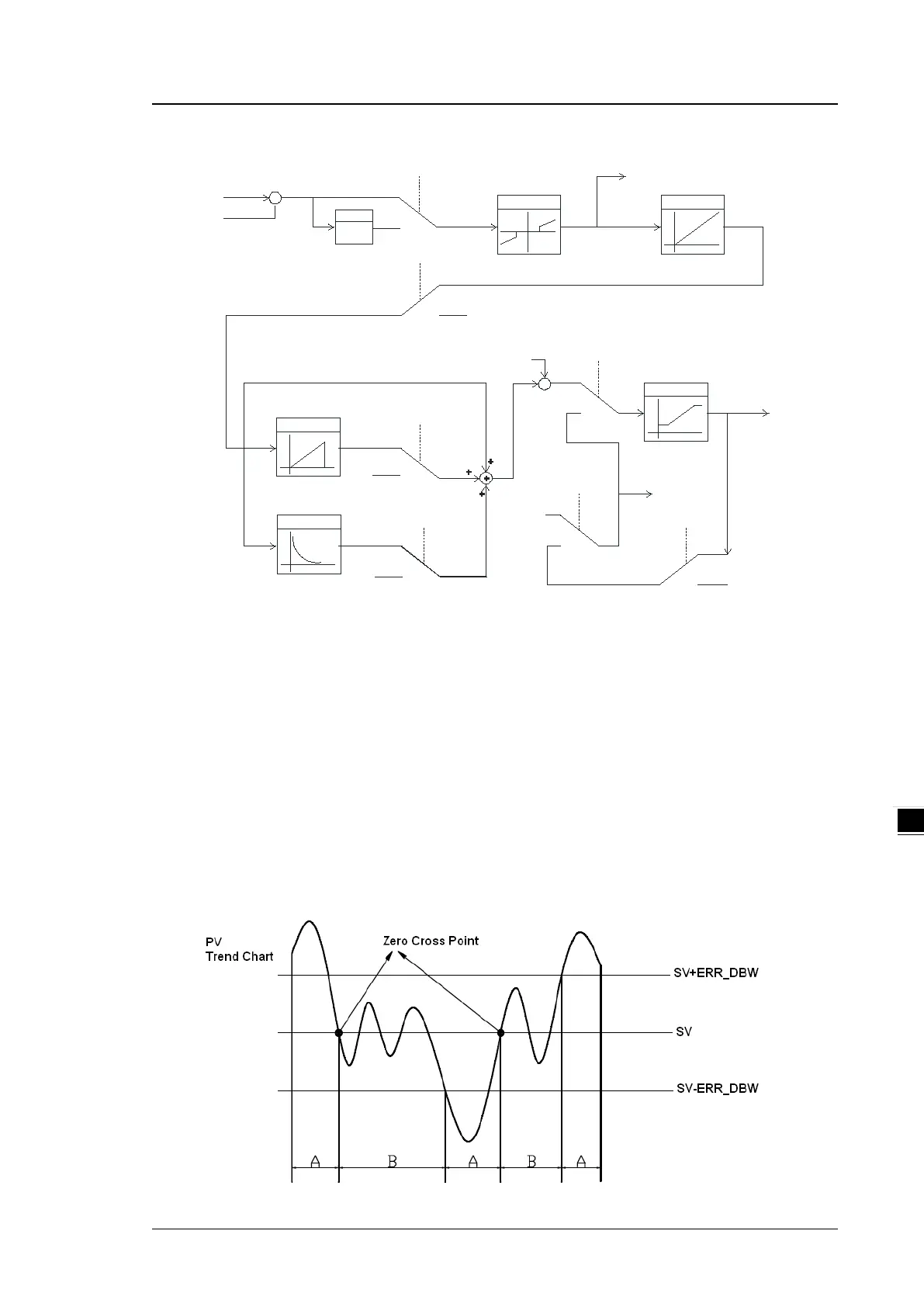
PID Block Diagram (Dependent)
SV
PV
+
-
+
PID-P
Kc_Kp
REVERSE
X(-1)
PID_DIR
0
1
E
DEAD BAND
ERR_DBW
PID-I
Ti_Ki
Kc_Kp
>0
<=0
0
Ti_Ki
>0
<=0
0
PID-D
Td_Kd, Tf
0
>0
<=0
Td_Kd
BIAS
PID_MAN
+
+
+
MV
MV_LIMIT
MV_MAX, MV_MIN
MOUT_AUTO
MOUT
MOUT
PID_MAN
MOUT
0
1
0
1
0
1
ERR_DBW
When the PV (present value) is in the range of ERR_DBW, at the beginning, the present error is brought
into the PID algorithm according to the normal processing, and then the CPU module checks whether the
present error meets the cross status condition: PV (present value) goes beyond the SV (target value).
Once the condition is met, the present error is counted as 0 when applying the PID algorithm. After the PV
(present value) is out of the ERR_DBW range, the present error is brought into the PID algorithm again. If
PID_DE is true, that means it uses the variations in the PV to calculate the control value of the derivative,
and after the cross status condition is met, the PLC treats Δ PV as 0 to apply the PID algorithm. (Δ PV=
current PV – previous PV). In the following example, the present error is brought into the PID algorithm
according to the normal processing in section A ,and the present error or Δ PV is counted as 0 to apply
the PID algorithm in the section B.
 Loading...